12
8 Maintenance mode
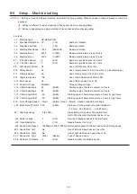
Maintenance mode consists of items as shown below.
Machine Test
Movement test, maintenance, and adjustment
Machine Setting
Machine control setting
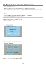
Memory All Clear
Initialization of design memory.
Main Program Update Update of operation program and language data
Machine Program Update
Update of control program and frame move data
Frame Position Entry
Registration of coordinates for positioning sensor
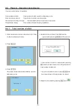
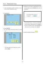
Record
Total number of stitches, Error occurrence record, Occurrence record by
error type.
Maintenance Register Registration of machine maintenance date(Normally not used at maintenance)
Other
Other (This item is neither configured nor used)
License Registration
Limited usable period
Replaced CONT Board
―
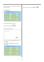
Machine Setting Navigation after exchanging CONT board (Main program Ver.*1.34~)
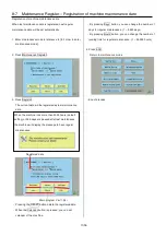
8-1 How to enter maintenance mode
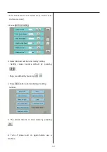
1. Turn on machine.
2. Press NEXT while pressing START/STOP button
at the screen of the control box after booting
the machine.
Main program Ver.*1.34~
3. Press
.
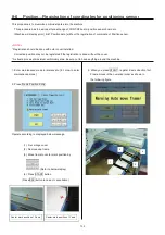
You can enter maintenance mode again by long key
press of
(Menu) at the Drive screen after
maintenance mode is finished.
However, you cannot use the reentry method above
once the machine is turned off and rebooted.
Summary of Contents for HCD2-1501-40
Page 1: ...Maintenance Manual for Embroidery Machine HCD2 1501 40 Version 2 3 HappyJapan Inc ...
Page 10: ...10 HSA90311 Shell alvania EP Grease2 100g Page 31 33 36 M0404342 Needle height gauge Page 52 ...
Page 150: ...143 10 1 Electrical connection diagram before Rev A for LCD CE board 1 3 ...
Page 151: ...144 10 1 Electrical connection diagram before Rev A for LCD CE board 2 3 ...
Page 152: ...145 10 1 Electrical connection diagram before Rev A for LCD CE board 3 3 ...
Page 153: ...146 10 2 Electrical connection diagram before Rev A for LCD CE U LCD CE MX board 1 4 ...
Page 154: ...147 10 2 Electrical connection diagram before Rev A for LCD CE U LCD CE MX board 2 4 ...
Page 155: ...148 10 2 Electrical connection diagram before Rev A for LCD CE U LCD CE MX board 3 4 ...
Page 156: ...149 10 2 Electrical connection diagram before Rev A for LCD CE U LCD CE MX board 4 4 ...
Page 157: ...149a 10 2a Electrical connection diagram Rev A 1 4 ...
Page 158: ...149b 10 2a Electrical connection diagram Rev A 2 4 ...
Page 159: ...149c 10 2a Electrical connection diagram Rev A 3 4 ...
Page 160: ...149d 10 2a Electrical connection diagram Rev A 4 4 ...
Page 161: ...150 10 3 Connection of inverter Inverter set Inverter set ...
Page 165: ...153 HCD8116 TP SW Circuit Board Ass y HCD8124 TC8 7 Circuit Board Ass y Rev A ...
Page 166: ...154 HCD8119 y ...


