123
8-2 Machine Test Machine movement
Below operation will be moved solely. In some operations, actuator of motor will be moved, Keep hands and face away during
movement for your own safety.
#
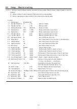
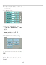
1 Needle Adjust : Input of Needle bar detect Potentiometer
At section of [Setting to detect needle position], this
function can be used to set position of Potentiometer.
#2 Cutter Adjust : Action test of moving knife Open-Close
Use this function to adjust stop position of Moving knife.
#3 Catcher Adjust : Action test of Thread catch hook
This test is used to adjust stop position of Thread catch
hook.
#4 Keeper Test : Action test of Keeper solenoid ON-OFF
This test is used to check action of Keeper.
#5 Jump Solenoid Test : Movement test of jump device
ON-OFF.
This test is used to check movement of Jump device.
#6 Catcher Test : Movement test of thread catch hook
IN-OUT
Use this test to check movement of Thread catch hook.
#7 Cutter Test : Action test of moving knife Open-Close
Use this function to check opening-closing action of
Moving knife.
#8 Clip Solenoid : Action test of clip type thread holder
(Option)
This test is used to check movement of clip type thread
holder.
#9 Pointer Test : Action test of laser pointer (Option)
This test is used to check action of Laser pointer.
#10 Fan Drive Test : Action test of cooling fan ON-OFF
Use this function to check movement of cooling fan.
#11 Encoder Check : Input test of L point / C point timing
With turning main shaft, you can use this function to
check if L point signal, C point signal, and timing signal
are correct or not.
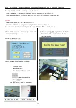
#12 Position Data Entry : Position Data Entry Confirm frame
moving sensor
This test is used to check action of Frame moving
sensor.
From Main program Ver.*1.34~, the Pulse motor will be
un-locked when you activate the test, then you can
move the embroidery frame to your desire position.
#13 Position Data Entry : Confirm registration of frame
position data
You can use this function to check if Frame position data
are entered correctly.
#14 Shaft Drive Test : Main shaft control test
You can turn main shaft with pushing “Start” or “Jump”
key of Needle bar section.
This function can be used for test run after maintenance
work.
#15 Sequin test (Option)
This test is used to check or adjust of Sequin device.
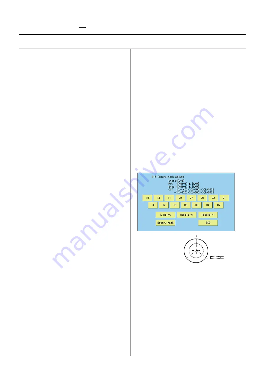
#16 Rotary Hook Adjust
(
Main program Ver.*1.37~
)
This function can be used for [Adjustment of
needle height] or [Adjustment of rotary hook
timing].
40, 220 degrees
160, 340 degrees 100, 280 degrees
[01]–[15]: Needle change
[L point]: Main shaft will turn and set Needle bar
position for [Adjustment of needle height] (L+5
degree).
[Rotary hook]: Rotary hook will turn and stop every
120 degrees to access 3 fixing screws easier.
[Ndl +1],[Ndl -1]: Needle bar moves to the left or
right, then sets Needle bar position for
[Adjustment of needle height] (L+5 degree).
#17 Needle Posi. Adjust
(Not used in HCD2)
Summary of Contents for HCD2-1501-40
Page 1: ...Maintenance Manual for Embroidery Machine HCD2 1501 40 Version 2 3 HappyJapan Inc ...
Page 10: ...10 HSA90311 Shell alvania EP Grease2 100g Page 31 33 36 M0404342 Needle height gauge Page 52 ...
Page 150: ...143 10 1 Electrical connection diagram before Rev A for LCD CE board 1 3 ...
Page 151: ...144 10 1 Electrical connection diagram before Rev A for LCD CE board 2 3 ...
Page 152: ...145 10 1 Electrical connection diagram before Rev A for LCD CE board 3 3 ...
Page 153: ...146 10 2 Electrical connection diagram before Rev A for LCD CE U LCD CE MX board 1 4 ...
Page 154: ...147 10 2 Electrical connection diagram before Rev A for LCD CE U LCD CE MX board 2 4 ...
Page 155: ...148 10 2 Electrical connection diagram before Rev A for LCD CE U LCD CE MX board 3 4 ...
Page 156: ...149 10 2 Electrical connection diagram before Rev A for LCD CE U LCD CE MX board 4 4 ...
Page 157: ...149a 10 2a Electrical connection diagram Rev A 1 4 ...
Page 158: ...149b 10 2a Electrical connection diagram Rev A 2 4 ...
Page 159: ...149c 10 2a Electrical connection diagram Rev A 3 4 ...
Page 160: ...149d 10 2a Electrical connection diagram Rev A 4 4 ...
Page 161: ...150 10 3 Connection of inverter Inverter set Inverter set ...
Page 165: ...153 HCD8116 TP SW Circuit Board Ass y HCD8124 TC8 7 Circuit Board Ass y Rev A ...
Page 166: ...154 HCD8119 y ...


