137
9-1-2 Setting procedure
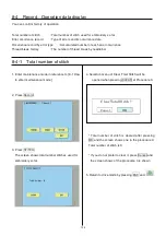
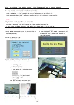
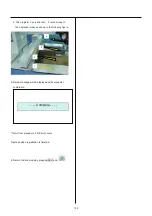
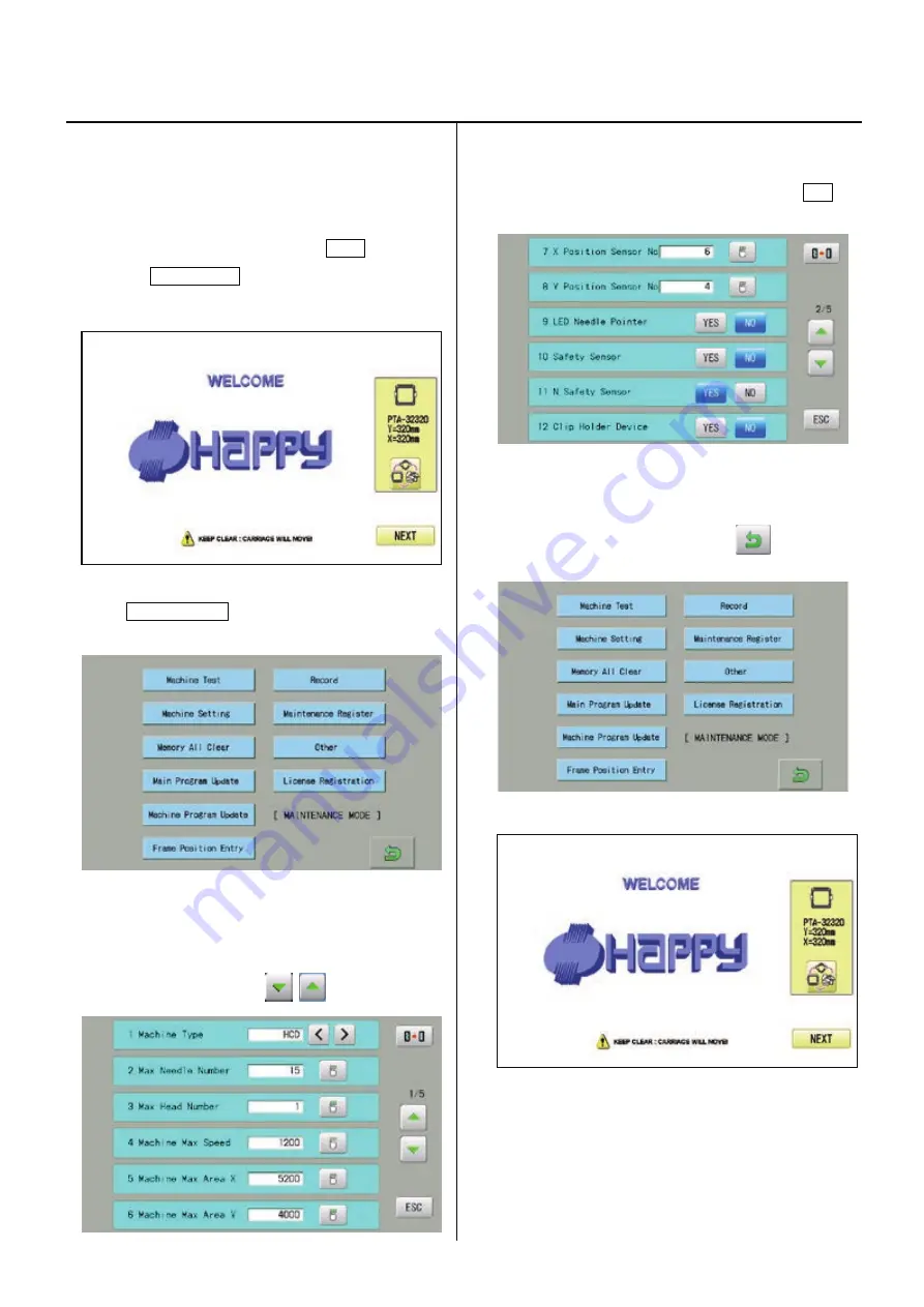
1. Turn on machine.
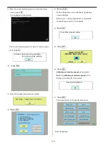
2. To access maintenance mode, press NEXT while
pressing START/STOP button at the startup screen of
the control box after booting the machine.
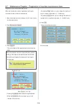
3.
Press Machine Setting.
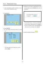
4.
Select “YES” on 11 [N. Safety Sensor]
Page is switched by pressing
.
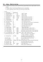
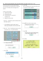
5. After safety sensor setting is complete, return to
the [MAINTENANCE MODE] screen by pressing ESC.
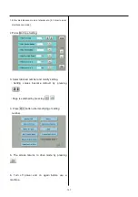
6.
To return to the startup screen, press
.
Safety sensor setting procedure is done.
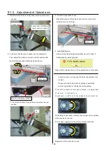
次に、
sensor
の adjustment of optical axis を行って下さい。
Summary of Contents for HCD2-1501-40
Page 1: ...Maintenance Manual for Embroidery Machine HCD2 1501 40 Version 2 3 HappyJapan Inc ...
Page 10: ...10 HSA90311 Shell alvania EP Grease2 100g Page 31 33 36 M0404342 Needle height gauge Page 52 ...
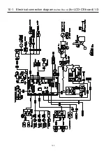
Page 150: ...143 10 1 Electrical connection diagram before Rev A for LCD CE board 1 3 ...
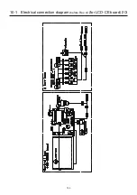
Page 151: ...144 10 1 Electrical connection diagram before Rev A for LCD CE board 2 3 ...
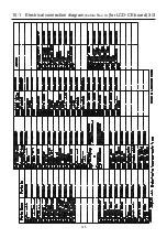
Page 152: ...145 10 1 Electrical connection diagram before Rev A for LCD CE board 3 3 ...
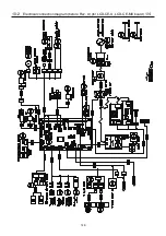
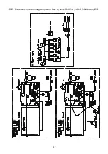
Page 153: ...146 10 2 Electrical connection diagram before Rev A for LCD CE U LCD CE MX board 1 4 ...
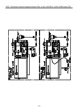
Page 154: ...147 10 2 Electrical connection diagram before Rev A for LCD CE U LCD CE MX board 2 4 ...
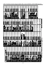
Page 155: ...148 10 2 Electrical connection diagram before Rev A for LCD CE U LCD CE MX board 3 4 ...
Page 156: ...149 10 2 Electrical connection diagram before Rev A for LCD CE U LCD CE MX board 4 4 ...
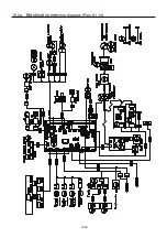
Page 157: ...149a 10 2a Electrical connection diagram Rev A 1 4 ...
Page 158: ...149b 10 2a Electrical connection diagram Rev A 2 4 ...
Page 159: ...149c 10 2a Electrical connection diagram Rev A 3 4 ...
Page 160: ...149d 10 2a Electrical connection diagram Rev A 4 4 ...
Page 161: ...150 10 3 Connection of inverter Inverter set Inverter set ...
Page 165: ...153 HCD8116 TP SW Circuit Board Ass y HCD8124 TC8 7 Circuit Board Ass y Rev A ...
Page 166: ...154 HCD8119 y ...

