138
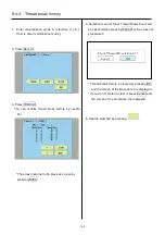
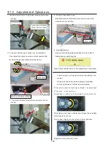
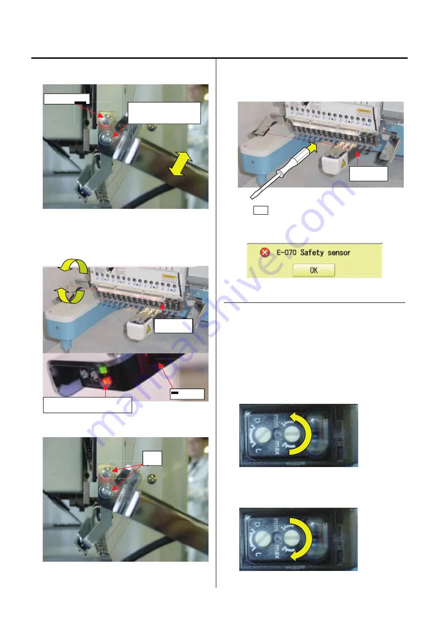
9-1-3 Adjustment of Optical axis
1.
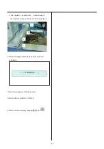
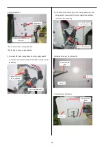
Loosen screws that are fixing
Safety sensor optical receiver
(Left side).
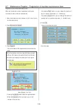
2. To be sure that the way of sensor ray is not blocked.
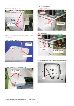
Then, adjust the optical receiver to correct position that
the LED (Orange) light stable as picture below.
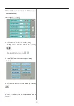
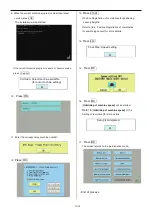
3.
Fix screws that are fixing
Safety sensor optical receiver
(Left side).
4.
Confirm of operation check.
Block Optical axis of Needle sensor at drive mode (Use
screwdriver or something)
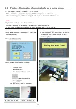
5.
Press Start button.
Below error will be displayed and Machine won’t start if
Needle sensor works properly.
Press [OK] to release the error, then adjustment is completed.
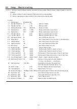
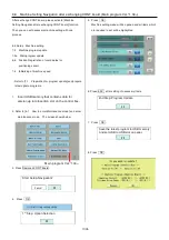
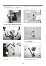
In some cases, you may need to adjust sensibility of the
receiver.
Please note that factory default setting of sensibility
volume (right side) is “middle” as picture below.
If the safety sensor detects upper thread, the adjustment
of receiver is toosensitive.
In such case, slightly turn the volume to [min] direction.
If the safety sensor does not detect even finger, the sensibility
of the receiver is too low.
In such case, slightly turn the volume to [max] direction
.
Adjustment of Optical axis is done.
Loosen slightly
Loosen screw until Safety
sensor can move slightly
Lamp for receiving ray
(orange)
Ray receiver
Optical axis
Optical axis
Fix
Summary of Contents for HCD2-1501-40
Page 1: ...Maintenance Manual for Embroidery Machine HCD2 1501 40 Version 2 3 HappyJapan Inc ...
Page 10: ...10 HSA90311 Shell alvania EP Grease2 100g Page 31 33 36 M0404342 Needle height gauge Page 52 ...
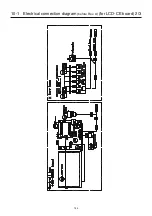
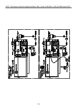
Page 150: ...143 10 1 Electrical connection diagram before Rev A for LCD CE board 1 3 ...
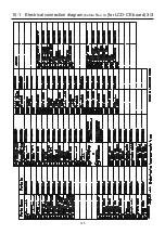
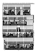
Page 151: ...144 10 1 Electrical connection diagram before Rev A for LCD CE board 2 3 ...
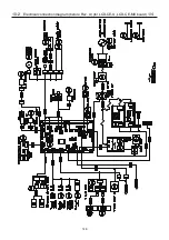
Page 152: ...145 10 1 Electrical connection diagram before Rev A for LCD CE board 3 3 ...
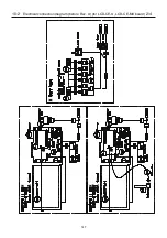
Page 153: ...146 10 2 Electrical connection diagram before Rev A for LCD CE U LCD CE MX board 1 4 ...
Page 154: ...147 10 2 Electrical connection diagram before Rev A for LCD CE U LCD CE MX board 2 4 ...
Page 155: ...148 10 2 Electrical connection diagram before Rev A for LCD CE U LCD CE MX board 3 4 ...
Page 156: ...149 10 2 Electrical connection diagram before Rev A for LCD CE U LCD CE MX board 4 4 ...
Page 157: ...149a 10 2a Electrical connection diagram Rev A 1 4 ...
Page 158: ...149b 10 2a Electrical connection diagram Rev A 2 4 ...
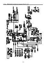
Page 159: ...149c 10 2a Electrical connection diagram Rev A 3 4 ...
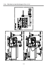
Page 160: ...149d 10 2a Electrical connection diagram Rev A 4 4 ...
Page 161: ...150 10 3 Connection of inverter Inverter set Inverter set ...
Page 165: ...153 HCD8116 TP SW Circuit Board Ass y HCD8124 TC8 7 Circuit Board Ass y Rev A ...
Page 166: ...154 HCD8119 y ...


