158
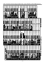
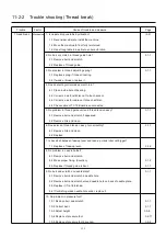
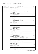
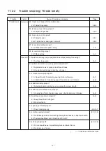
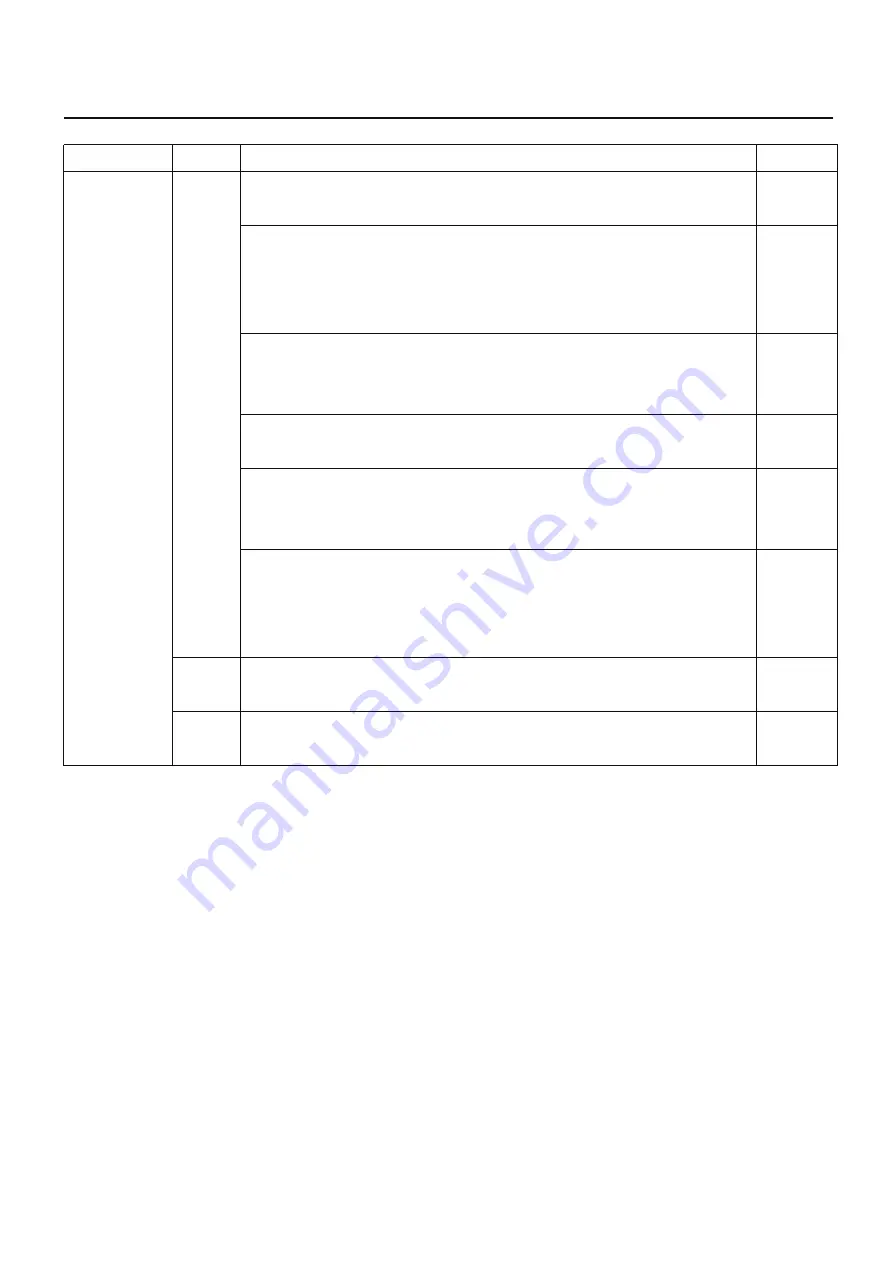
11-2-1 Trouble shooting (Electricity doesn’t turn on)
Trouble Factor Cause of trouble and measure
Page
Electricity
Mechanical
1. Did fuse blow?
doesn't turn on 1-1 If it did, replace it. 4-1
2. Check of defect on board.
2-1 Replace of LCD-CE board.
2-2 Replace of LCD unit.
2-3 Replace of CONT-D2 board 5-2
3. No problem in power supply?
3-1 Check and adjust the correct voltage.
4-3-2, 3
3-2 Try to replace power supply. 4-3-1
4. Check Volume of the power failure detection fit with CONT-D2 board.
4-1 Adjust of power failure detection. 4-4-4
5. Check of Cable catching causes short-circuit.
5-1 Please insulate the cable after removing outer cover.
5-2 Replace of cable.
6. Confirm not getting power supply from same outlet with other embroidery
machine or other machines which contains motor.
6-1 Preferably only 1 embroidery machine should be connected with 1 outlet.
(Maximum 2-3machines)
Operator 1. Didn't press emergency switch?
(3-8)
1-1 Release lock.
Environment
1. Is electricity in receptacle?
1-1 Supply power.
( ) ----- Reference instruction book
Summary of Contents for HCD2-1501-40
Page 1: ...Maintenance Manual for Embroidery Machine HCD2 1501 40 Version 2 3 HappyJapan Inc ...
Page 10: ...10 HSA90311 Shell alvania EP Grease2 100g Page 31 33 36 M0404342 Needle height gauge Page 52 ...
Page 150: ...143 10 1 Electrical connection diagram before Rev A for LCD CE board 1 3 ...
Page 151: ...144 10 1 Electrical connection diagram before Rev A for LCD CE board 2 3 ...
Page 152: ...145 10 1 Electrical connection diagram before Rev A for LCD CE board 3 3 ...
Page 153: ...146 10 2 Electrical connection diagram before Rev A for LCD CE U LCD CE MX board 1 4 ...
Page 154: ...147 10 2 Electrical connection diagram before Rev A for LCD CE U LCD CE MX board 2 4 ...
Page 155: ...148 10 2 Electrical connection diagram before Rev A for LCD CE U LCD CE MX board 3 4 ...
Page 156: ...149 10 2 Electrical connection diagram before Rev A for LCD CE U LCD CE MX board 4 4 ...
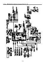
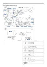
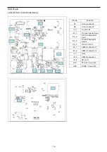
Page 157: ...149a 10 2a Electrical connection diagram Rev A 1 4 ...
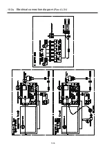
Page 158: ...149b 10 2a Electrical connection diagram Rev A 2 4 ...
Page 159: ...149c 10 2a Electrical connection diagram Rev A 3 4 ...
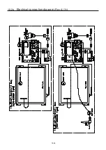
Page 160: ...149d 10 2a Electrical connection diagram Rev A 4 4 ...
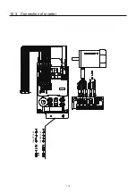
Page 161: ...150 10 3 Connection of inverter Inverter set Inverter set ...
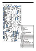
Page 165: ...153 HCD8116 TP SW Circuit Board Ass y HCD8124 TC8 7 Circuit Board Ass y Rev A ...
Page 166: ...154 HCD8119 y ...

