168
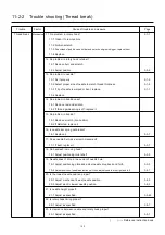
11-2-4
Tro
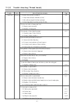
uble shooting (Off-registration of pattern)
Trouble Factor Cause of trouble and measure
Page
Off-registration Operator 2. Is cloth properly stretched.
(6-2) (7-5)
of pattern 2-1 Stretch properly.
3. Is thread tension proper?
(4-5) (8-1)
3-1 Observing sewing rhythm, set thread tension properly.
4. Was the machine left for a long time in middle of sewing?
4-1 Try to finish sewing as soon as possible.
Environment
1. Is strength of table and floor enough?
(2-2)
1-1 Check where to place the machine again.
1-2 Move to where floor is strong enough.
1-3 Use strong table to be able to endure vibration.
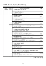
2. No problem in pulse motor driver by low power and voltage (variation)?
2-1 Supply rated voltage. (23-1)
2-2 Use transformer.
2-3 Use stabilizer.
3. Is there no place where noise is generated near the machine?
3-1 Don't use the machine near where noise is generated.
4. Doesn't drive frame hit obstacle?
4-1 Remove obstacle.
4-2 When useing cap frame, see not to hit table.
(7-2)
Thread & 1. Not using shrinkable cloth?
(4-3)
cloth 1-1 Use backing paper (consider number of sheets to use).
2. Isn't breakable cloth is used by thread tightening?
(4-3)
2-1 Use backing paper (consider number of sheets to use).
3. Is proper backing paper used?
(4-3)
3-1 Use backing paper to match cloth.
4. Isn't cloth (embroidery) too heavy?
4-1 Don't use extremely heavy cloth.
Pattern
1. Pattern data may be destroyed.
(5-6)
1-1 Read again.
1-2 Let new pattern read.
2. Memory pattern was destroyed.
(5-6)
2-1 Let new pattern read.
3. No problem in floppy disc or memory card?
3-1 Initialize and read again. (5-5)
3-2 Prepare new floppy disc or memory card.
( ) ----- Reference instruction book
Summary of Contents for HCD2-1501-40
Page 1: ...Maintenance Manual for Embroidery Machine HCD2 1501 40 Version 2 3 HappyJapan Inc ...
Page 10: ...10 HSA90311 Shell alvania EP Grease2 100g Page 31 33 36 M0404342 Needle height gauge Page 52 ...
Page 150: ...143 10 1 Electrical connection diagram before Rev A for LCD CE board 1 3 ...
Page 151: ...144 10 1 Electrical connection diagram before Rev A for LCD CE board 2 3 ...
Page 152: ...145 10 1 Electrical connection diagram before Rev A for LCD CE board 3 3 ...
Page 153: ...146 10 2 Electrical connection diagram before Rev A for LCD CE U LCD CE MX board 1 4 ...
Page 154: ...147 10 2 Electrical connection diagram before Rev A for LCD CE U LCD CE MX board 2 4 ...
Page 155: ...148 10 2 Electrical connection diagram before Rev A for LCD CE U LCD CE MX board 3 4 ...
Page 156: ...149 10 2 Electrical connection diagram before Rev A for LCD CE U LCD CE MX board 4 4 ...
Page 157: ...149a 10 2a Electrical connection diagram Rev A 1 4 ...
Page 158: ...149b 10 2a Electrical connection diagram Rev A 2 4 ...
Page 159: ...149c 10 2a Electrical connection diagram Rev A 3 4 ...
Page 160: ...149d 10 2a Electrical connection diagram Rev A 4 4 ...
Page 161: ...150 10 3 Connection of inverter Inverter set Inverter set ...
Page 165: ...153 HCD8116 TP SW Circuit Board Ass y HCD8124 TC8 7 Circuit Board Ass y Rev A ...
Page 166: ...154 HCD8119 y ...

