170
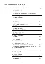
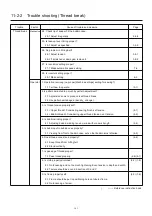
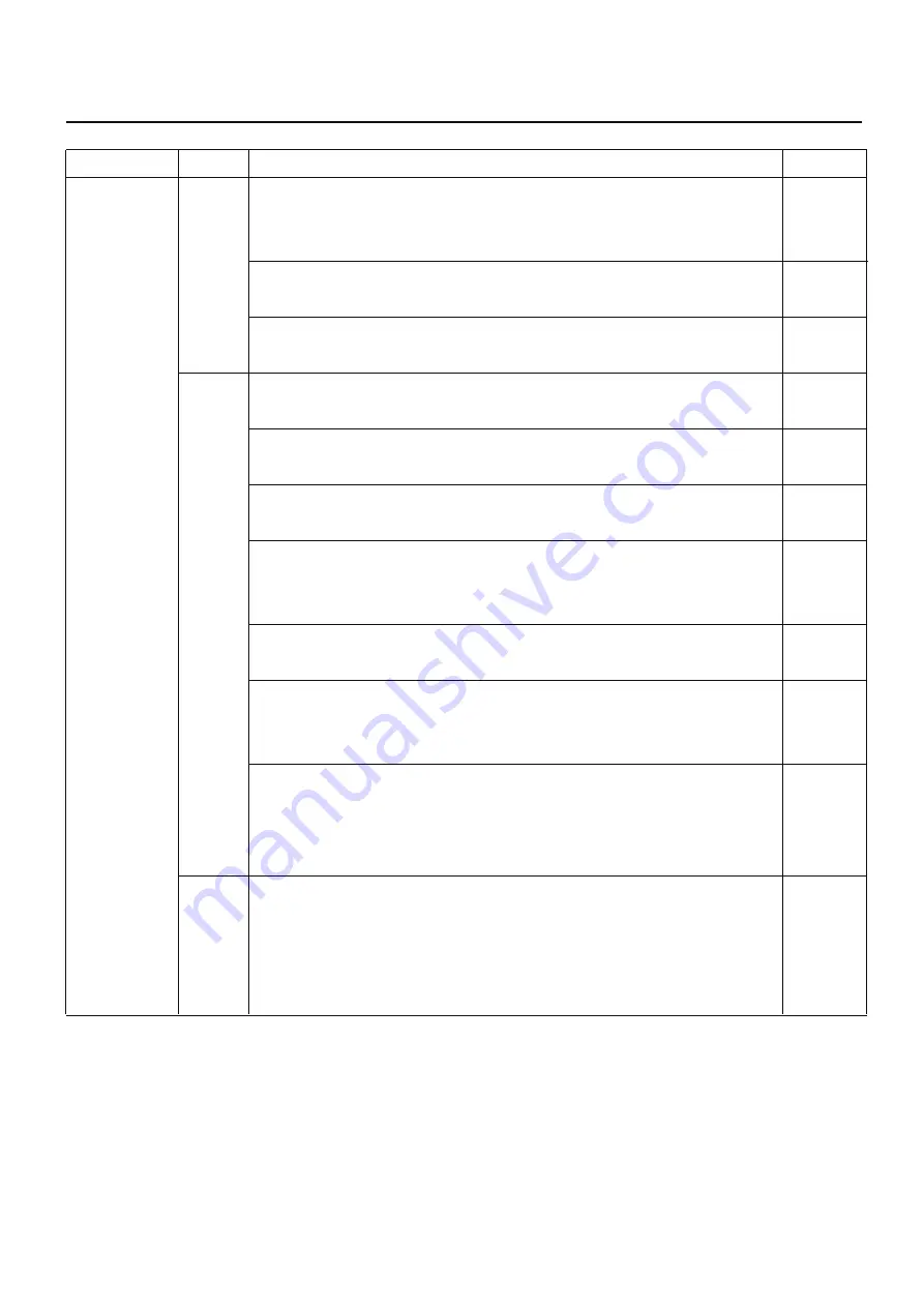
11-2-5 Trouble shooting (Upper thread comes off from needle hole)
Trouble Factor Cause of trouble and measure
Page
Upper thread
Mechanical
10.Check the needle bar moves when start sewing.
comes off 12-1 Adjust position to fix jump device.
3-2-5
from needle 12-2 Replace needle bar driver.
3-2-4
hole 11. Is number of revolution proper when sewing started?
13-1 Make automatic speed setting.
7-4
12.Is height of pressure foot proper?
14-1 Adjust as specified.
3-2-9
Operator 1. Isn't thread tension too strong?
(4-5) (8-1)
1-1 Weaken tension not to cause trouble in sewing rhythm.
2. Keen in cleaning thread cut device?
(23-2)
2-1 Clean bobbin thread holder regularly.
3. Is setting of bobbin thread proper?
(4-5)
3-1 Pass thread on bobbin thread guide surely.
4. Is bobbin thread properly wound?
(4-4) (4-5)
4-1 Adjust tensile strength of bobbin winder and check holding plate.
4-2 Pull out bobbin thread to check if it comes out smoothly.
5. Is upper thread properly passed?
(4-6) (4-7)
5-1 Pass properly again.
6. Does thread cone stand properly?
(4-6)
6-1 Keep thread from hitting felt.
6-2 Stand vertically.
7. Is [Machine settings] properly set?
(5-1)
7-1 Select setting of length of TRD. Cut [Long].
7-2 Select setting of Quick start mode [No].
7-3 Select setting of STR. Lock stitch [Yes].
Thread & 1. Is thread used to suit embroidery? (thread twist, tender thread).
3-1-3
Cloth 1-1 Don't use too strongly twisted thread.
1-2 Twist of thread is to be left-wise.
1-3 Use tender thread.
1-4 Don't use thread with knot or uneven size.
( ) ----- Reference instruction book
Summary of Contents for HCD2-1501-40
Page 1: ...Maintenance Manual for Embroidery Machine HCD2 1501 40 Version 2 3 HappyJapan Inc ...
Page 10: ...10 HSA90311 Shell alvania EP Grease2 100g Page 31 33 36 M0404342 Needle height gauge Page 52 ...
Page 150: ...143 10 1 Electrical connection diagram before Rev A for LCD CE board 1 3 ...
Page 151: ...144 10 1 Electrical connection diagram before Rev A for LCD CE board 2 3 ...
Page 152: ...145 10 1 Electrical connection diagram before Rev A for LCD CE board 3 3 ...
Page 153: ...146 10 2 Electrical connection diagram before Rev A for LCD CE U LCD CE MX board 1 4 ...
Page 154: ...147 10 2 Electrical connection diagram before Rev A for LCD CE U LCD CE MX board 2 4 ...
Page 155: ...148 10 2 Electrical connection diagram before Rev A for LCD CE U LCD CE MX board 3 4 ...
Page 156: ...149 10 2 Electrical connection diagram before Rev A for LCD CE U LCD CE MX board 4 4 ...
Page 157: ...149a 10 2a Electrical connection diagram Rev A 1 4 ...
Page 158: ...149b 10 2a Electrical connection diagram Rev A 2 4 ...
Page 159: ...149c 10 2a Electrical connection diagram Rev A 3 4 ...
Page 160: ...149d 10 2a Electrical connection diagram Rev A 4 4 ...
Page 161: ...150 10 3 Connection of inverter Inverter set Inverter set ...
Page 165: ...153 HCD8116 TP SW Circuit Board Ass y HCD8124 TC8 7 Circuit Board Ass y Rev A ...
Page 166: ...154 HCD8119 y ...

