3
Index
page
For safe adjustment and repair 2
Index
3
Special tool, Measuring equipment, Other 8
1 Outline of mechanism
1-1 Outline of mechanical mechanism.
11
1-2 Placement of key electronic parts
13
2 Outer covers
2-1 Removal of
thread guide ass’y, thread guide pillar and thread stand.
11
2-2 Removal of outer covers.
13
3 Mechanical mechanism.
3-1 Basic maintenance.
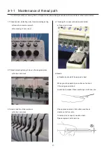
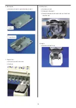
3-1-1 Maintenance of thread path.
17
3-1-2 Fixing of needle.
19
3-1-3 Selection of thread.
20
3-1-4 Relation between needle and upper thread.
21
3-2 Fixed head.
3-2-1 Exchange of crank ass’y.
22
3-2-2 Exchange of rod.
30
3-2-3 Exchange of
pressure foot arm ass'y
32
3-2-4 Exchange of
pressure foot cam.
33
3-2-5 Adjustment of the lowest needle point.
35
3-2-6 Exchange of needle bar driver.
36
3-2-7 Adjustment of fixing of jump device
37
3-2-8 Exchange of roller shaft ass’y. 38
3-2-9 Adjustment of take-up lever timing.
39
3-2-10 Check of height of pressure foot.
40
3-2-11 Exchange / Adjustment of pressure foot
41
3-2-12 Fixing of
thread catcher.
43
Summary of Contents for HCD2-1501-40
Page 1: ...Maintenance Manual for Embroidery Machine HCD2 1501 40 Version 2 3 HappyJapan Inc ...
Page 10: ...10 HSA90311 Shell alvania EP Grease2 100g Page 31 33 36 M0404342 Needle height gauge Page 52 ...
Page 150: ...143 10 1 Electrical connection diagram before Rev A for LCD CE board 1 3 ...
Page 151: ...144 10 1 Electrical connection diagram before Rev A for LCD CE board 2 3 ...
Page 152: ...145 10 1 Electrical connection diagram before Rev A for LCD CE board 3 3 ...
Page 153: ...146 10 2 Electrical connection diagram before Rev A for LCD CE U LCD CE MX board 1 4 ...
Page 154: ...147 10 2 Electrical connection diagram before Rev A for LCD CE U LCD CE MX board 2 4 ...
Page 155: ...148 10 2 Electrical connection diagram before Rev A for LCD CE U LCD CE MX board 3 4 ...
Page 156: ...149 10 2 Electrical connection diagram before Rev A for LCD CE U LCD CE MX board 4 4 ...
Page 157: ...149a 10 2a Electrical connection diagram Rev A 1 4 ...
Page 158: ...149b 10 2a Electrical connection diagram Rev A 2 4 ...
Page 159: ...149c 10 2a Electrical connection diagram Rev A 3 4 ...
Page 160: ...149d 10 2a Electrical connection diagram Rev A 4 4 ...
Page 161: ...150 10 3 Connection of inverter Inverter set Inverter set ...
Page 165: ...153 HCD8116 TP SW Circuit Board Ass y HCD8124 TC8 7 Circuit Board Ass y Rev A ...
Page 166: ...154 HCD8119 y ...


