10
7
Remove LCD-CE board
4-1-1
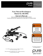
1. Remove four setscrews as shown in the figure below
and remove rear cover.
2. Remove connectors for SW cable, Box cable, cable for
LCD inverter (red/white).
SW cable Box cable
Cable for LCD inverter (red/white)
3. Remove set screw and sealed case A.
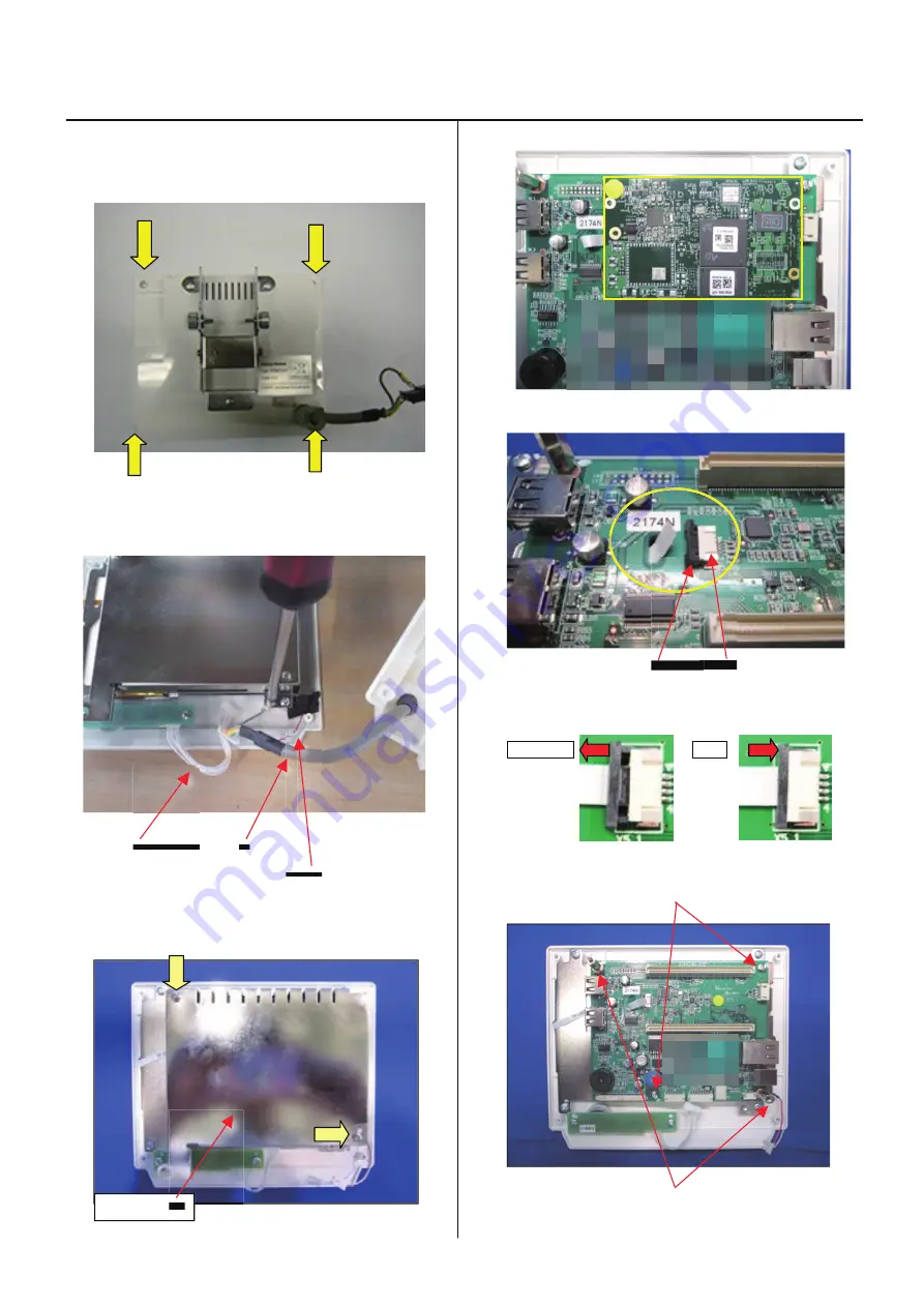
4. Remove core module.
5. Remove narrow flat cable for LCD unit.
Latch Connector
When you pull the latch to cord side, the cord release.
When you push the latch to connector side, the cord fixed
.
Release Fix
6. Remove two sets screws and two studs.
Screws
Stud
Sealed case A
Summary of Contents for HCH-701-30
Page 1: ...Maintenance Manual for Embroidery Machine HCH 701 30 Version 2 4 HappyJapan Inc ...
Page 132: ...128 Electrical connection diagram 5 ...
Page 133: ...129 Electrical connection diagrams 5 ...
Page 134: ...130 List of electrical connection diagrams 5 ...
Page 137: ...130c HCD81222 LCD CE MX 基板組 ...
Page 138: ...130d HCD8116 TP switch board ass y 3 82 7 32 7 387487 2487 ...