1
12
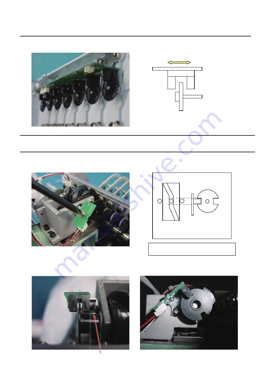
Adjustment of TC board
4-2-2
Viewing from side of circuit board, set slit so that it comes to center of sensor has to be same as the picture below.
Adjustment of stop position of needle bar change unit
4-2-3
Sensor board
Set position where sensor on sensor board and slit don't cross to area where moving head doesn't move
when turning groove cam.
Fixing screw for slit
Imagine figure of position sensor and cam
Summary of Contents for HCH-701-30
Page 1: ...Maintenance Manual for Embroidery Machine HCH 701 30 Version 2 4 HappyJapan Inc ...
Page 132: ...128 Electrical connection diagram 5 ...
Page 133: ...129 Electrical connection diagrams 5 ...
Page 134: ...130 List of electrical connection diagrams 5 ...
Page 137: ...130c HCD81222 LCD CE MX 基板組 ...
Page 138: ...130d HCD8116 TP switch board ass y 3 82 7 32 7 387487 2487 ...


