14
Removal of outer covers
(CONTROL BOX)
2-1
<Check>
Be sure to turn power switch OFF before
work.
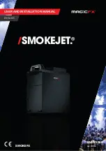
1. Remove three setscrews of arm E as shown in the
figure
below.
2. Disconnect the connectors indicated by the arrows in
the figure below. Remove the screw that fixes cables.
3. Remove two screws on arm D as shown in the figure
below.
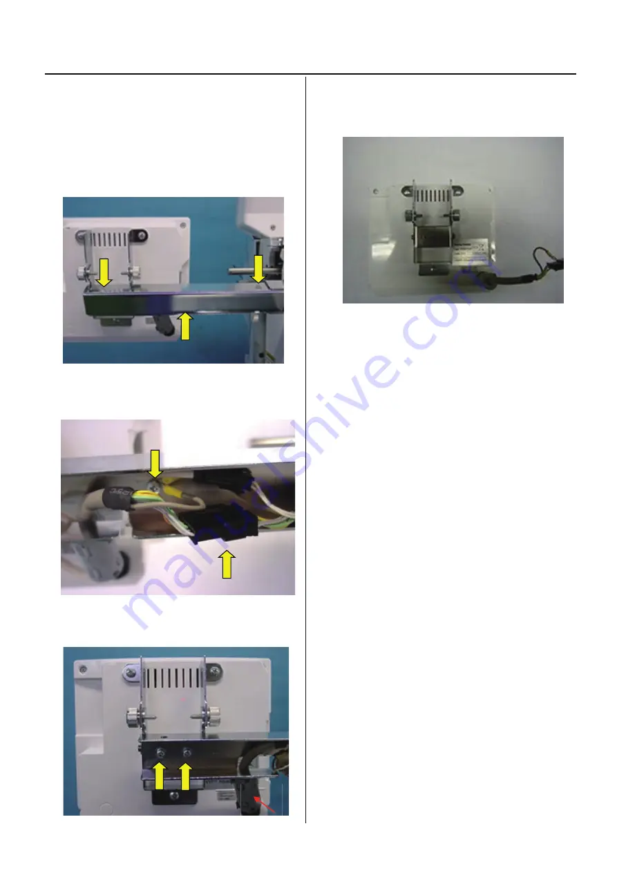
4.
Remove control box.
Summary of Contents for HCH-701-30
Page 1: ...Maintenance Manual for Embroidery Machine HCH 701 30 Version 2 4 HappyJapan Inc ...
Page 132: ...128 Electrical connection diagram 5 ...
Page 133: ...129 Electrical connection diagrams 5 ...
Page 134: ...130 List of electrical connection diagrams 5 ...
Page 137: ...130c HCD81222 LCD CE MX 基板組 ...
Page 138: ...130d HCD8116 TP switch board ass y 3 82 7 32 7 387487 2487 ...