24
Exchange of crank
3-2-1
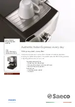
7. Remove thread catcher ass’y
8. Remove face plate on the left.
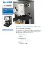
9. Referring to [3-2-4 Exchange of needle bar driver],
remove needle bar driver ass’y.
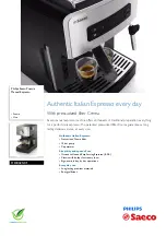
10. Remove Bobbin winder.
11. Remove power supply.
Cable 2 pcs, Screw 2 pcs
Power supply
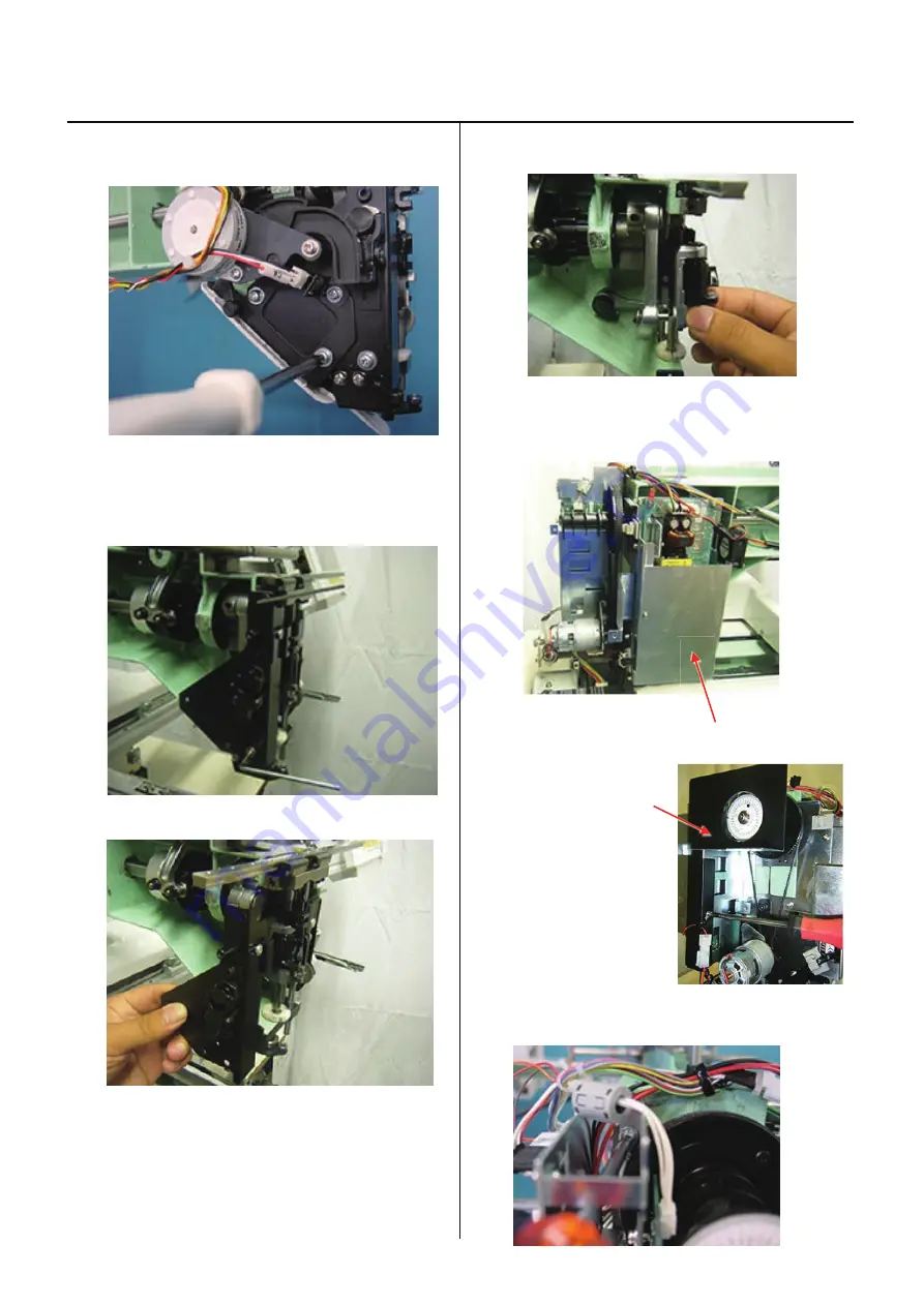
12.
Remove Cover.
Cover
13. Remove circuit board assembly for timing detecting
board. Cable 1 pcs, Screw 2 pcs
Summary of Contents for HCH-701-30
Page 1: ...Maintenance Manual for Embroidery Machine HCH 701 30 Version 2 4 HappyJapan Inc ...
Page 132: ...128 Electrical connection diagram 5 ...
Page 133: ...129 Electrical connection diagrams 5 ...
Page 134: ...130 List of electrical connection diagrams 5 ...
Page 137: ...130c HCD81222 LCD CE MX 基板組 ...
Page 138: ...130d HCD8116 TP switch board ass y 3 82 7 32 7 387487 2487 ...