34
Exchange of roller shaft ass’y
3-2-7
1.
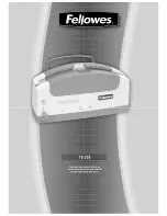
Remove take-up lever crank.
Push take-up lever shaft by slender shaft.
(Hexagon wrench etc.)
Shaft Plain washer (M6) Take-up lever crank
<Attention>
Machine number ~1082003 is having a Plain washer
(M6) between Shaft and Take-up lever crank.
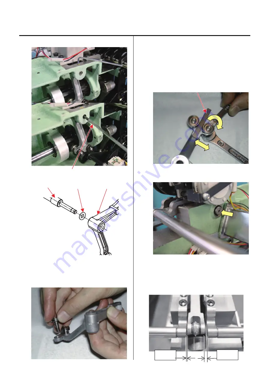
2. Exchange roller shaft ass’y.
<Spanner> 7mm, 8mm
3. Insert bering positioning gauge [
4.85mm
] between bering
and bering , and then tighten roller shaft ass’y.
Please adjust roller shaft for machine front side ways.
This roller shaft ass’y is eccentricity.
Turn lean screw and just touch roller to gauge.
Bering positioning gauge [
4.85mm
]
4. Return take-up lever crank ass’y to previous place to
finish.
Please push to arrow ways until stop.
<Attention>
Although the Take-up lever crank is assembled to
the left side, but it is correct.
h
ha
0.5mm
2.5mm
Summary of Contents for HCH-701-30
Page 1: ...Maintenance Manual for Embroidery Machine HCH 701 30 Version 2 4 HappyJapan Inc ...
Page 132: ...128 Electrical connection diagram 5 ...
Page 133: ...129 Electrical connection diagrams 5 ...
Page 134: ...130 List of electrical connection diagrams 5 ...
Page 137: ...130c HCD81222 LCD CE MX 基板組 ...
Page 138: ...130d HCD8116 TP switch board ass y 3 82 7 32 7 387487 2487 ...