


7
8
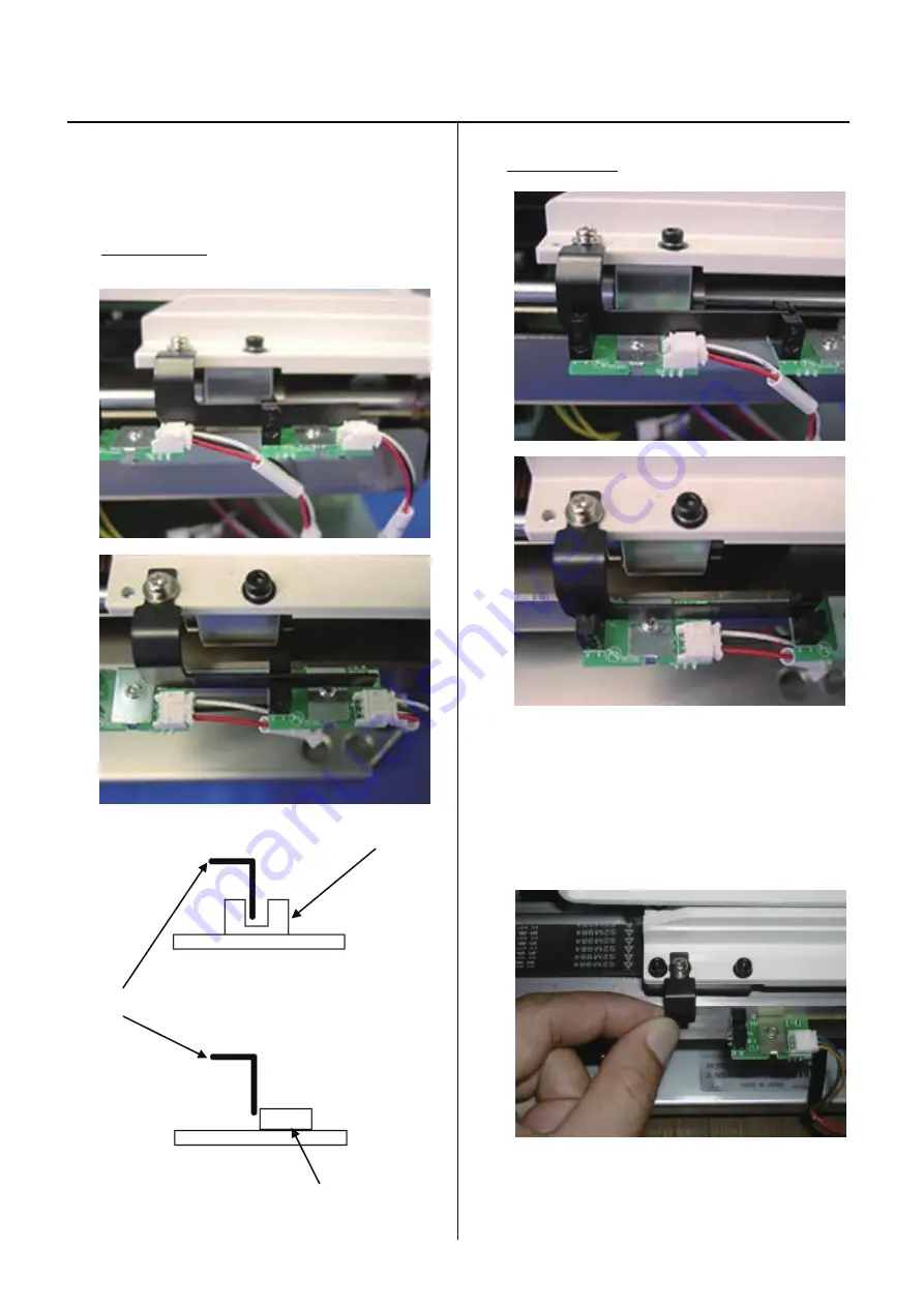
Assemble the arm ass’y
3-6-1
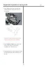
6. Check of interference between detecting plate and sensor
or connector of sensor board.
A part of sensor
Sensor
Detecting plate
Conector
A part or conector
7. Adjust by bending detecting plate by hand if you find
any interference with sensor or connector.
8. Finish this process.
Summary of Contents for HCH-701-30
Page 1: ...Maintenance Manual for Embroidery Machine HCH 701 30 Version 2 4 HappyJapan Inc ...
Page 132: ...128 Electrical connection diagram 5 ...
Page 133: ...129 Electrical connection diagrams 5 ...
Page 134: ...130 List of electrical connection diagrams 5 ...
Page 137: ...130c HCD81222 LCD CE MX 基板組 ...
Page 138: ...130d HCD8116 TP switch board ass y 3 82 7 32 7 387487 2487 ...


