46
4-2-2 Assemble and remove moving head (1
st
Head)
2.
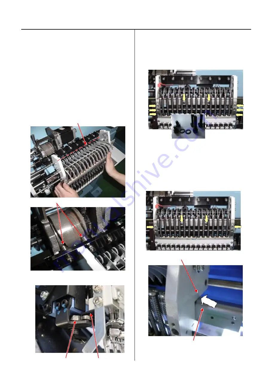
Install moving head.
2-1. When you install moving head, please set the same
position of Needle bar change unit as the position which
you took Moving head out. (slightly moved to the right
position then 15th needle)
< Note >
In case you lost the position mentioned above:
Please turn power on and move moving head to 14th
needle by Needle change button, then move to 15th
needle.
After setting to 15th needle, please move slightly to the
right by knob of Needle bar change unit.
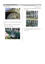
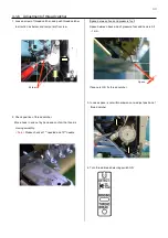
Guide bar
Cam follower
With turning knob, set the rail into Positioning Rollers.
Positioning roller Rail
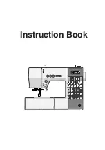
2-2. Set moveing head to 15th needle position and
temporally tighten screws.
(Hexagon socket head cap screw : M4-20 6 pcs)
(Hexagon socket head cap screw : M4-6 2 pcs)
Please put plain washer with hexagon socket head cap
screw.
2-3. Move moving head to the position that 8
th
needle is
active.
Tighten 4 screws on moving head. (see photo below)
Moving head
Rail support
Please confirm that there is no space at the arrow point on
above picture.
Summary of Contents for HCR3-1502
Page 1: ... Maintenance Manual for Embroidery Machine HCR3E SERIES Version 1 2 HappyJapan Inc ...
Page 104: ...105 4 7 3 Adjustment of timing detecting unit 8 Finally put the cover back on ...
Page 107: ...107 ...
Page 172: ...172 E7 Electric system diagram E7 1 Pulse motor driver PMD wiring ...
Page 173: ...173 E7 2 Pulse motor driver PMD setup ...
Page 174: ...174 E7 3 Inverter wiring ...
Page 175: ...175 E7 4 Electrical connection diagram ...
Page 176: ...176 ...
Page 177: ...177 ...
Page 178: ...178 E7 5 List of electrical connection diagram ...
Page 179: ...179 ...
Page 180: ...180 E7 6 Explanation of function clrcuit board HCD8122 LCD CE MX Board Ass y ...
Page 181: ...181 HCD8116 TP SW Circuit Board Ass y CN No Function CN1 Switch output LED input ...


