background image

6

Instalación

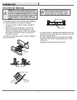
OPCIONES DE MONTAJE

ADVERTENCIA:

 Para reducir el riesgo de incendio, descarga eléctrica 

o lesiones personales, monta el ventilador sobre una caja eléctrica 

marcada como “aprobada como soporte de ventiladores de 35 lb (15,9 

kg) o menos”, y usa los tornillos de montaje que vienen con la misma. 

Las cajas eléctricas utilizadas comúnmente para el soporte de artículos 

de iluminación pueden no servir como soporte de ventilador, y tal 

vez deban reemplazarse. En caso de duda, consulta a un electricista 

calificado.

Si tu ventilador de techo no tiene una caja de montaje aprobada por 
UL, instala una siguiendo las instrucciones a continuación:


Desconecta la energía retirando los fusibles o apagando los 
cortacircuitos.


Asegura la caja eléctrica directamente a la estructura del 
edificio. Usa sujetadores y materiales apropiados. La caja 
eléctrica y su soporte deben poder sostener el peso completo 
del ventilador en movimiento (al menos 35 lb). No uses una 
caja eléctrica de plástico.

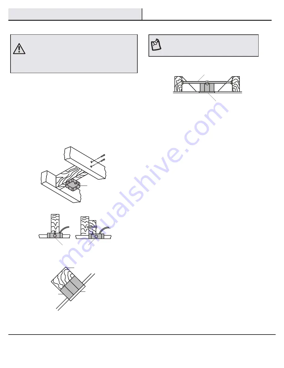
Las ilustraciones a continuación muestran tres formas distintas de 
montar la caja eléctrica.

Si la cubierta (C) toca el ensamblaje del tubo bajante/bola (B), retira la 
tapa inferior decorativa de la cubierta y gira la cubierta (C) 180º antes 
de fijarla a la placa de montaje.
Para colgar el ventilador donde ya haya una lámpara pero ninguna 
viga de techo, tal vez necesites una barra colgante como se mostró 
anteriormente
(disponible en cualquier tienda de The Home Depot).

NOTA: 

Tal vez necesites un tubo bajante más largo para 

mantener la altura mínima adecuada de las aspas, al 
instalar el ventilador en un techo inclinado. El ángulo 
máximo permitido es de 28º de la posición horizontal.

Caja 

Eléctrica

Caja Eléctrica

Caja 

Eléctrica 

Empotrada

Soporte Fuerte

Placa 

de Montaje 

en Techo

Caja Eléctrica

Barra para Colgar

Summary of Contents for MARLOWE

Page 1: ...PTONBAY COM THANK YOU We appreciate the trust and confidence you have placed in Hampton Bay through the purchase of this ceiling fan We strive to continually create quality products designed to enhanc...

Page 2: ...stallation WARNING To reduce the risk of personal injury do not bend the blade brackets also referred to as flanges during assembly or after installation Do not insert objects in the path of the blade...

Page 3: ...l render the warranty invalid There is no other express warranty Hampton Bay hereby disclaims any and all warranties including but not limited to those of merchantability and fitness for a particular...

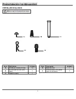
Page 4: ...nt screws 16 BB Plastic wire connecting nut 3 CC Hanger pin 1 Part Description Quantity DD Locking pin 1 EE Blade bracket screw with lockwasher 11 Pre Installation continued HARDWARE INCLUDED NOTE Har...

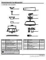
Page 5: ...embly 1 F Light kit pan 1 Part Description Quantity G Blade 5 H Blade bracket 5 I Light kit fitter assembly 1 J Glass bowl 1 K Remote control receiver batteries included 1 L CFL light bulb 14 Watt max...

Page 6: ...ppropriate fasteners and materials The outlet box and its bracing must be able to fully support the weight of the moving fan at least 35 lbs Do not use a plastic outlet box The illustrations below sho...

Page 7: ...in CC until it snaps into its locked position Re tighten the setscrew HH on the collar on top of the fan motor assembly E Remove the canopy ring O from the canopy C by turning the ring to the right un...

Page 8: ...tlet box Note that the flat side of the mounting bracket A is toward the outlet box Securely tighten the two mounting screws UU Carefully lift the fan motor assembly E up to the slide on mounting brac...

Page 9: ...on your remote control Controller Model FAN28R 240W NOTE This remote is equipped with a 16 code combination To prevent possible interference from or to other remote units such as garage door openers...

Page 10: ...to the receiver NN white wire LL using a plastic wire connecting nut BB Connect the fan motor black wire KK to the receiver NN black wire KK using a plastic wire connecting nut BB Connect the fan mot...

Page 11: ...tachment screws AA Tighten each blade attachment screw AA securely Attach the blade assembly to the fan motor assembly E by aligning the two holes of blade bracket H with the two holes of the fan moto...

Page 12: ...fan motor assembly E with the white wire from the top of the light kit fitter assembly I Attach the light kit fitter I to the light kit pan F by securing them with the two screws P loosened in the fi...

Page 13: ...n and reverse the airflow 1 Speed The remote features Low Med Hi and Off buttons to select the desired speed of operation and turn the fan On or Off 2 Light To control the light kit the remote feature...

Page 14: ...lade levels are unequal Check this level by selecting a point on the ceiling above the tip of one of the blades Measure from a point on the center of each blade to the point on the ceiling Measure thi...

Page 15: ...Questions problems missing parts Before returning to the store call Hampton Bay Customer Service 8 a m 6 p m EST Monday Friday 1 877 527 0313 HAMPTONBAY COM Retain this manual for future use...

Page 16: ...13 HAMPTONBAY COM GRACIAS POR TU COMPRA Apreciamos la confianza que has depositado en Hampton Bay al comprar este ventilador de techo Nos esforzamos para continuamente crear productos de calidad dise...

Page 17: ...ENCIA Para reducir el riesgo de lesiones personales no dobles los soportes de las aspas tambi n llamados bridas durante o despu s de la instalaci n No coloques objetos en la trayectoria de las aspas A...

Page 18: ...sonas no autorizadas anular la garant a No hay ninguna otra garant a expresa Mediante la presente Hampton Bay se exime de cualquier garant a incluyendo pero sin limitarse a aquellas de comercializaci...

Page 19: ...pl stico para conectar cables 3 CC Pasador de soporte 1 Pieza Descripci n Cantidad DD Pasador de cierre 1 EE Tornillo adicional para soporte de aspas con contratuerca 11 t Preinstalaci n continuaci n...

Page 20: ...1 F Carcasa del kit de luces 1 Pieza Descripci n Cantidad G Aspa 5 H Soporte de aspa 5 I Ensamblaje del soporte del kit de luces 1 J Taz n de vidrio 1 K Control remoto receptor bater as incluidas 1 L...

Page 21: ...ujetadores y materiales apropiados La caja el ctrica y su soporte deben poder sostener el peso completo del ventilador en movimiento al menos 35 lb No uses una caja el ctrica de pl stico Las ilustraci...

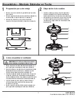
Page 22: ...l pasador de sujeci n CC hasta que quede encajado en su posici n Vuelve a apretar los tornillos HH del collar n ubicados en la parte superior del ensamblaje del motor del ventilador E Retira el aro O...

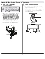
Page 23: ...ado plano del soporte de montaje A est hacia la caja el ctrica Ajusta firmemente los dos tornillos de montaje UU Con cuidado alza el ensamblaje del motor del ventilador E hasta el soporte de montaje d...

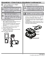
Page 24: ...del Controlador FAN28R 240W NOTA Este control remoto est equipado con 16 combinaciones de c digos Para evitar posibles interferencias desde o hacia otras unidades de control remoto como los abrepuert...

Page 25: ...del ventilador LL al cable blanco LL del receptor NN usando un conector de cables pl stico BB Conecta el cable negro del motor del ventilador KK al cable negro KK del receptor NN usando un conector de...

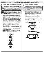
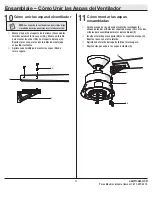
Page 26: ...e montaje de aspas AA restantes Aprieta cada tornillo para montar las aspas AA de forma segura Coloca el aspa en la carcasa del motor del ventilador E alineando los dos orificios del soporte del aspa...

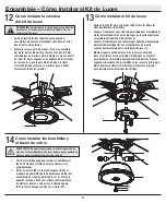
Page 27: ...ilador E con el cable blanco de la parte superior del ensamblaje del soporte del kit de luces I Monta el soporte del kit de luces I en la carcasa del kit de luces F y f jalo con los dos tornillos P af...

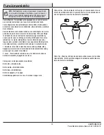
Page 28: ...remoto tiene teclas de Bajo Medio Alto y Apagado para seleccionar la velocidad de funcionamiento deseada y para apagar o encender el ventilador 2 Luces Para controlar el kit de luces el control remot...

Page 29: ...st n seguros La mayor a de los problemas de oscilaci n del ventilador se deben a que las aspas no est n a un mismo nivel Verifica este nivel seleccionando un punto en el techo sobre la punta de una de...

Page 30: ...iezas faltantes Antes de regresar a la tienda llama al Servicio al Cliente de Hampton Bay de Lunes a Viernes entre 8 a m y 6 p m Hora del Este de EE UU 1 877 527 0313 HAMPTONBAY COM Conserva este manu...

Reviews: