PM-200 POWER SUPPLY MODULE INSTALLATION INSTRUCTIONS
PARTS SUPPLIED WITH THIS KIT:
(1) PM-200 Power Supply Module Circuit Board
(1) 3.6k
Ω
¼-Watt Resistor
(8)
1N5408
Diodes
(1)
1
Ω
3-Watt Resistor
(14) 1M
Ω
¼-Watt
Resistors
(12)
82k
Ω
3-Watt Resistors
(6) 180
μ
F 450VDC Electrolytic Capacitors
(1) 910
Ω
2-Watt Resistor
(1) 15K
Ω
½-Watt Resistor
(1) #20 5" Small Blue Wire
To start the installation, read these instructions very carefully. Unplug the amplifier and remove any
input, output and control cables that may be connected to the back of the amplifier. Remove the
chassis from the case and remove the perforated sheet metal RF shield from the top of the chassis.
Remove the tubes and place them in a safe place. You are now ready to proceed with the
installation.
( )
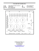
Assemble the PM-200 Power Module according to the parts layout diagram. Make sure
resistors R1A-R6B are mounted approximately ¼” above the PC board. All other components
are mounted flush to the PC board. In addition, solder one end of the 5” #20
BLUE
wire to the
underside of the PC board at pad
“V”
.
( )
Place the amplifier on its side (transformer down). Unsolder all wires connected to the power
supply circuit board. These are the
RED
and
RED & YELLOW
transformer wires on the top
side of the circuit board, a
GRAY
wire and a
YELLOW
wire from the top side of the board
(these wires pass through the hole in the circuit board), the
(3) 4.7M
Ω
resistor assembly
on
the bottom of the circuit board and the heavy
BLUE
HV wire on the bottom side of the board.
( )
Remove the fixed end of the (3) 4.7M
Ω
resistor assembly from the terminal strip lug and
discard these resistors
.
( )
Remove the (9) #6-32x3/8” screws, washers and nuts that secure the circuit board in place.
Save this hardware.
( )
Place the amplifier right side up and remove the 5 control knobs from their shafts.
( )
Remove the 3 nuts and washers that secure the bandswitch, meter switch and sensitivity
potentiometer and save them.
( )
Remove the (4) #6-32x3/8” Phillips-head screws, washers and nuts that secure the front
panel. Save this hardware.
( )
Gently tilt the front panel forward. You may have to carefully pry it loose with a small
screwdriver because the paint from the front panel may stick to the chassis. Place the front
panel down in front of the chassis.
( )
Lift the circuit board from the front so that it tilts upward about 1”.
( )
Using diagonal cutters, cut the old circuit board from the front left corner all the way back to
the wire hole. This will break out a path for the wires to exit. Be careful not to cut any wires
during this process. This will free the old circuit board so that is can be removed without
further unsoldering of wires.
1
Summary of Contents for PM-200
Page 3: ...3 ...


