( )
Carefully work the old circuit board out of the compartment and discard it.
( )
Take the new circuit board and work it into position with the wires passing through the slot in
the board.
( )
Secure the board on the right side with 2 or 3 of the #6-32x3/8” screws, washers and nuts.
Tighten enough to hold the board. They will be adjusted later.
( )
Reinstall the
YELLOW
and
GRAY
wires in their marked holes in the circuit board and solder.
( )
Swing the front panel back into position and reinstall the (4) #6-32x3/8” Phillips-head screws,
washers and nuts.
( )
Reinstall the 3 control flat washers and nuts and tighten.
( )
With the amplifier on its side (transformer down), install the remaining #6-32x3/8” screws,
washers and nuts holding the circuit board in place. Tighten all screws. You will have one
screw left over.
( )
Put the
RED
and
RED & YELLOW
transformer wires through their appropriate holes in the
circuit board and solder.
( )
Place the amplifier upside down.
( )
Locate the 2-lug terminal strip just to the rear of the new circuit board. Remove the 15K
Ω
resistor and clean the holes in the terminal strip lugs.
Note: There is still a blue wire
connected to the insulated terminal lug.
( )
Connect the 5” #20
BLUE
wire connected to hole
“V”
on the circuit board to the insulated lug
of the terminal strip.
DO NOT
solder yet.
( )
Connect the supplied 15K
Ω
½-watt resistor between the 2 lugs of the terminal strip. Solder all
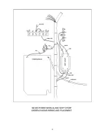
connections (See pictorial).
( )
Solder the heavy
BLUE
HV wire to the circle pad marked
“H”
on the underside of the circuit
board.
( )
Carefully inspect all work. Replace the front panel knobs (make sure they are properly aligned
with the front panel markings).
( )
Reinstall the tubes and the perforated sheet metal RF shield on the top of the chassis and put
the chassis back into the case.
This completes the installation of the PM-200 power supply module. It will provide you with a better
power supply that provides the necessary B+ filtering and regulation. Your amplifier should not
experience any power supply problems in the future.
2
Summary of Contents for PM-200
Page 3: ...3 ...


