background image

16

CARE AND MAINTENANCE

At least twice each year, tighten all screws on the fan . Clean the motor housing with only a soft brush 

or lint-free cloth to avoid scratching the finish. 

Bulb Replacement: Use 60-watt max . E26-base LED, CFL or incandescent bulbs . Halogen bulbs are 

not recommended for this item . 
Battery Replacement for Remote: Use A23 12-volt battery .

Important:

 Shut off the main power supply before you begin any maintenance tasks. Do not use 

water or a damp cloth to clean the ceiling fan .

TROUBLESHOOTING

PROBLEM

POSSIBLE CAUSE

CORRECTIVE ACTION

The fan does not 

move .

1 . 

The power is off or the fuse is 

blown .

2 .  There is a faulty wire 

connection .

3 .  The plugs are not connected 

properly .

4 .  The reverse switch is not 

completely engaged .

1 .  Turn the power on or check the 

fuse .

2 . 

Turn the power off. Loosen the 

canopy and check all connections .

3 .  Check that the connectors from 

the light kit and fan are connected 

properly .

4 .  Push the reverse switch completely 

to the left or right .

There is excessive 

wobbling .

1 .  The blades and/or blade arms 

are loose . 

2 .  The blades are unbalanced . 

3 .  The fan mounting is not secure .

1 .  Check and tighten all screws that 

hold the fan blades to the blade 

arms and the blade arms to the 

motor .

2 .  Switch one blade with a blade from 

the opposite side . Or balance the 

fan using the blade balancing kit (U) .

3 . 

Turn off the power. Loosen the 

motor housing and verify the upper 

mounting bracket is secure to the 

electrical outlet box . The bracket 

must be flush without movement 

against the outlet box .

The fan operates 

correctly, but the 

lights are not 

working .

1 .  The bulbs are not installed 

correctly .

2 .  The light kit wire plugs are not 

connected properly . 

3 .  There is a faulty wire 

connection .

1 .  Re-install the bulb(s) .

2 .  Ensure the single-pin connectors in 

the light kit are connected properly .

3 . 

Turn the power off and check all 

connections at the ceiling outlet box .

Summary of Contents for 0721899

Page 1: ... a m 6 p m EST Monday Thursday 8 a m 5 p m EST Friday 1 Harbor Breeze is a registered trademark of LF LLC All Rights Reserved ATTACH YOUR RECEIPT HERE Serial Number _________________________ Purchase Date _________________________ Español p 20 EB1690 ITEM 0803775 0721899 0807427 PAWTUCKET CEILING FAN MODEL 40958 40959 40047 ...

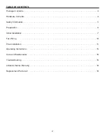
Page 2: ...3 Hardware Contents 4 Safety Information 5 Preparation 6 Initial Installation 7 Fan Wiring 10 Final Installation 11 Operating Instructions 15 Care and Maintenance 16 Troubleshooting 16 Limited Lifetime Warranty 18 Replacement Parts List 19 ...

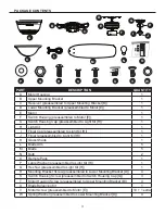
Page 3: ...Finial preassembled to Light Kit H 1 K Glass Shade 1 L Blade Arm 5 M Blade 5 N Bulb 2 O Remote Pack 1 P Large Washer preassembled to Light Kit H 1 Q Hex Nut preassembled to Light Kit H 1 R Mounting Bracket Screw preassembled to Lower Mounting Bracket D 4 S Switch Housing Screw preassembled to Switch Housing Cap G 3 T Motor Housing Screw preassembled to Upper Mounting Bracket B 4 U Blade Balancing ...

Page 4: ...4 HARDWARE CONTENTS shown actual size Plug Button Qty 1 Blade Screw Qty 15 1 extra Blade Washer Qty 15 1 extra Wire Connector Qty 2 AA BB CC DD ...

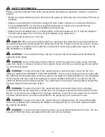
Page 5: ... loud humming noise from the fan To reduce the risk of fire or electric shock do NOT use a full range dimmer switch to control the fan speed WARNING To reduce the risk of fire electric shock or personal injury mount the fan to an outlet box marked ACCEPTABLE FOR FAN SUPPORT and use the mounting screws provided with the outlet box Most outlet boxes commonly used for the support of lighting fixtures...

Page 6: ...l interference to radio or television reception which can be determined by turning the equipment off and on The user is encouraged to try to correct the interference by one or more of the following measures Reorient or relocate the receiving antenna Increase the separation between the equipment and receiver Connect the equipment into and outlet on a circuit different from that to which the receive...

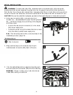
Page 7: ...th 2 Ensure the blades M will be at least 30 in from any obstructions and will be at least 7 ft above the floor 7 ft Min 30 in Min 3 Secure the upper mounting bracket B to the outlet box not included using screws and washers provided with the outlet box CAUTION It is very important that you use the proper hardware when installing the upper mounting bracket B as it will support the fan 2 B Outlet B...

Page 8: ...DD connect wires from receiver C preassembled to upper mounting bracket B and house supply wires according to the diagram and these steps Connect the red wire from receiver C to the black hot house supply wire Connect the white wire with red label from the receiver C to the white neutral house supply wire Note The remaining wires will be connected later in the installation process page 10 Hardware...

Page 9: ...nfusion during installation 8 Place one tab of the lower mounting bracket D into a slot in the upper mounting bracket B Then slide the second tab of the lower mounting bracket D into the second slot on the upper mounting bracket B until all four holes are in alignment 9 Re install the previously removed mounting bracket screws R and spring washers W to secure the lower mounting bracket D and the u...

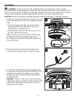
Page 10: ...e bare green ground house supply wire using a wire connector from remote pack O Connect the wire harness from the receiver C to the wire harness from the fan Note The green wire is the ground If house wires are different colors than referred to above it is recommended a professional electrician determines the proper wiring 2 Wrap electrical tape around each individual wire connector from remote pa...

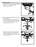
Page 11: ...motor E aligning the slotted holes in the motor housing A with the loosened motor housing screws T in the upper mounting bracket B Twist the motor housing A to lock Then re insert the two previously removed motor housing screws T and securely tighten all screws 3 Partially insert the blade screws BB along with the blade washers CC through the blade M and into the blade arm L Tighten each blade scr...

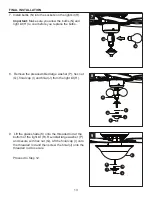
Page 12: ...rst remove the switch housing screws S preassembled to the switch housing cap G Then connect the single pin connectors from the switch housing F and switch housing cap G blue to black and white to white 6 Align the notch in the switch housing cap G with the reverse switch located on switch housing F Then assemble the switch housing cap G with light kit H to the switch housing F using the previousl...

Page 13: ...ove the preassembled large washer P hex nut Q finial cap I and finial J from the light kit H 9 Lift the glass shade K onto the threaded rod at the bottom of the light kit H Re install large washer P and secure with hex nut Q Lift the finial cap I onto the threaded rod and then screw the finial J onto the threaded rod to secure Proceed to Step 12 N H H P I Q J 7 8 K P Q I J 9 ...

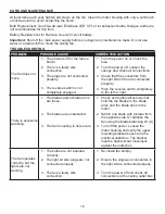
Page 14: ... AA into the center hole of the switch housing cap G 11 Remove the three switch housing screws S from the switch housing cap G and install the switch housing cap G onto the switch housing F Align the notch in the switch housing cap G with the reverse switch located on switch housing F then re install the three switch housing screws S 12 Turn on the power supply Assembly is complete 10 11 G G AA H ...

Page 15: ...ld light control to dim or brighten the lights CFL Bulbs Turns the lights on and off Note The dimmer function does not work with CFL bulbs 6 D CFL Switch Switch should be set to D to correspond with the included LED which will enable the dimming function Flip to CFL if you change to corresponding bulbs 3 Using a ceiling fan will allow you to raise your thermostat setting in summer and lower your t...

Page 16: ...ons 3 Check that the connectors from the light kit and fan are connected properly 4 Push the reverse switch completely to the left or right There is excessive wobbling 1 The blades and or blade arms are loose 2 The blades are unbalanced 3 The fan mounting is not secure 1 Check and tighten all screws that hold the fan blades to the blade arms and the blade arms to the motor 2 Switch one blade with ...

Page 17: ...e building structure 4 Ensure the mounting bracket is secured to the outlet box and that the screws are tight Remote doesn t work 1 LED indicator does not illuminate when remote button is pushed 2 The remote control is not synced with the fan s receiver 1 Replace the transmitter battery with a new 12 volt battery 2 Turn off the main power then turn it back on Within 30 seconds press and hold the h...

Page 18: ...varying climate conditions this warranty does not cover any changes in brass finish including rusting pitting corroding tarnishing or peeling Brass finishes of this type give their longest useful life when protected from varying weather conditions Any glass provided with this fan is not covered by the warranty Any replacement of defective parts from the ceiling fan must be reported within the firs...

Page 19: ...Mounting Bracket 0803775 B 0721899 B 0807427 B G Switch Housing Cap 0803775 G 0721899 G 0807427 G H Light Kit 0803775 H 0721899 H 0807427 H I Finial Cap 0803775 I 0721899 I 0807427 I J Finial 0803775 J 0721899 J 0807427 J K Glass Bowl 0803775 K 0721899 K 0807427 K L Blade Arm 0803775 L 0721899 L 0807427 L M Blade 0803775 M 0721899 M 0807427 M O Remote Pack 0803775 O 0721899 O 0807427 O HW Hardware...

Reviews: