background image

22

Printed in China

REPLACEMENT PARTS LIST

For replacement parts, call the customer service department at 1-800-643-0067, 8 a.m. - 6 p.m., EST,

Monday - Thursday, 8 a.m. - 5 p.m., EST, Friday.

PART

DESCRIPTION

0747603

PART #

0747604

PART #

A

Downrod

4L000011460

4L000011470

D

Mounting Bracket

4L000002480

4L000011480

E

Canopy

4L000011490

4L000011500

F

Canopy Cover

4L000011510

4L000011520

K

Light Kit

4L000011530

4L000011540

L

Finial Cap

4L000011550

4L000011560

M

Finial

4L000011570

4L000011580

N

Yoke Cover

4L000011590

4L000011600

P

Glass Bowl

4L167230001

4L167230001

R

Blade Arm

4L073950001

4L073950002

S

Blade

4L085370001

4L085370002

HW

Hardware Kit

4L000011610

4L000011620

9471 • 082219

D

E

A

F

K

L

M

N

HW

R

P

S

Summary of Contents for 0747603

Page 1: ...a m 6 p m EST Monday Thursday 8 a m 5 p m EST Friday ATTACH YOUR RECEIPT HERE Purchase Date _________________________ Harbor Breeze is a registered trademark of LF LLC All Rights Reserved BM19237 H ar...

Page 2: ...4 Safety Information 5 Preparation 6 Initial Installation 7 Standard or Angle Mounting Instructions 9 Wiring 12 Final Installation 13 Operating Instructions 18 Care and Maintenance 19 Troubleshooting...

Page 3: ...1 M Finial preassembled to Light Kit K 1 N Yoke Cover 1 O Bulb 2 P Glass Bowl 1 Q Adapter Plate Screw preassembled to Adapter Plate AB 3 R Blade Arm 5 S Blade 5 T Motor Screw preassembled to Motor As...

Page 4: ...ze Wire Connector Qty 3 1 extra Blade Screw Qty 15 1 extra Blade Washer Qty 15 1 extra Pull Chain Extension Qty 2 Plug Button Qty 1 Rubber Washer Qty 15 1 extra Motor Screw 1 extra AA XX EE BB CC GG D...

Page 5: ...oud humming noise from the fan To reduce the risk of fire or electric shock do NOT use a full range dimmer switch to control the fan speed WARNING To reduce the risk of fire electric shock or personal...

Page 6: ...eption which can be determined by turning the equipment off and on the user is encouraged to try to correct the interference by one or more of the following measures Reorient or relocate the receiving...

Page 7: ...style mounting is best suited for angled or vaulted ceilings A longer downrod is sometimes necessary to ensure proper blade clearance Note If using the angle mount check to ensure the ceiling angle i...

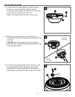
Page 8: ...to outlet box not included using screws and washers provided with the outlet box CAUTION It is very important to use the proper hardware when installing the mounting bracket D as this will support the...

Page 9: ...at the top of the motor assembly G 2 Insert the downrod A through the canopy E and yoke cover N Feed the wires from the motor assembly G through the downrod A 3 Slide the downrod A into the yoke of t...

Page 10: ...ed to cut back the lead wire in Step 4 strip 1 2 in of insulation from the end of the white wire Twist the stripped ends of each strand of wire within the insulation with pliers not included Repeat th...

Page 11: ...Align one of the four slots in the ball with the tab in the mounting bracket D Note The downrod A should not rotate if installed correctly DANGER Failure to align the slot in the downrod A with the ta...

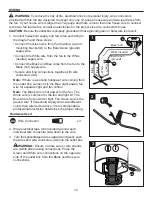
Page 12: ...ng connections together with wire connectors AA Note If there is a second hot power wire coming from the outlet box connect it to the Blue light power fan wire for separate light and fan control Note...

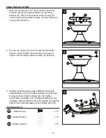
Page 13: ...viously removed Step 4 page 8 Tighten all mounting bracket screws U securely 3 Partially insert the blade screws BB along with the blade washers CC and rubber washers GG through the blade S and into t...

Page 14: ...e the other two screws 6 Insert the wires from the motor assembly G through the hole in the switch housing H Then attach the switch housing H to the adapter plate AB by twisting the switch housing H u...

Page 15: ...using cap I Then connect the single pin connector from the switch housing H to the single pin connector from the light kit K Blue to Blue and White to White Then secure the switch housing cap I with l...

Page 16: ...pull chain extensions DD or custom pull chain extensions not included to the fan and light pull chains Proceed to Step 14 Hardware Used DD Pull Chain Extension x 2 12 To install the fan without the l...

Page 17: ...rom the switch housing cap I Then attach the switch housing cap I to the switch housing H using the switch housing screws Z Attach the the pull chain extension DD to the pull chain Hardware Used DD Pu...

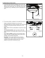
Page 18: ...ithout feeling a difference in your comfort Note Wait for the fan to stop before moving the reverse switch 2a In warmer weather push the reverse switch left which will result in downward airflow creat...

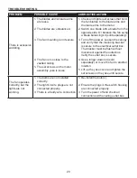
Page 19: ...itch is turned off 3 The power is off or the fuse breaker is blown 4 There is a faulty wire connection 1 Firmly push the reverse switch completely left or right 2 Make sure the wall switch is turned o...

Page 20: ...3 Turn off the power Loosen the canopy and verify that the mounting bracket is secure to the electrical outlet box The bracket must be flush without movement against the outlet box Verify the outlet b...

Page 21: ...arying climate conditions this warranty does not cover any changes in brass finish including rusting pitting corroding tarnishing or peeling Brass finishes of this type give their longest useful life...

Page 22: ...11470 D Mounting Bracket 4L000002480 4L000011480 E Canopy 4L000011490 4L000011500 F Canopy Cover 4L000011510 4L000011520 K Light Kit 4L000011530 4L000011540 L Finial Cap 4L000011550 4L000011560 M Fini...

Reviews: