background image

13

OPERATING INSTRUCTIONS

1.  The fan pull chain has four positions to control fan 

speed. One pull is HIGH, two is MEDIUM, three is 

LOW and four turns the fan OFF. 
The light pull chain has two positions to control the 

light, ON and OFF.

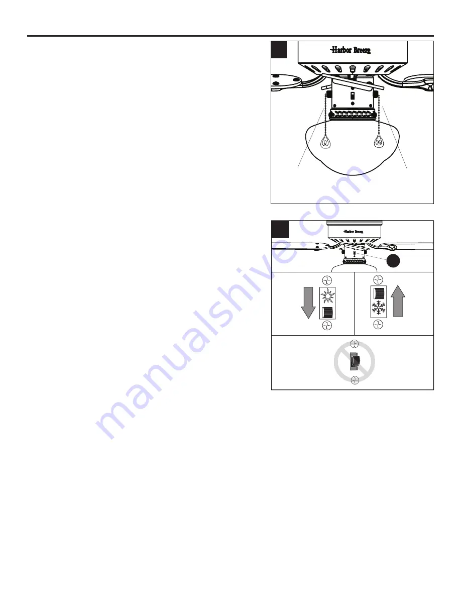
2.  Use the fan reverse switch, located on the switch 

housing (D), to optimize your fan for seasonal 

performance.
Using a ceiling fan will allow you to raise your 

thermostat setting in summer and lower your 

thermostat setting in winter without feeling a 

difference in your comfort.

Note:

 Wait for the fan to stop before moving the 

reverse switch.
2a. 

In warmer weather

, push the reverse switch down 

to display a sun icon, which will result in downward 

airflow creating a wind chill effect. 

2b. 

In cooler weather,

 push the reverse switch up to 

display a snowflake icon, which will result in upward 

airflow that can help move stagnant, hot air off the 

ceiling area.

Important:

 The reverse switch must be set either

completely up or down in order for the fan to function

correctly. If the reverse switch is set in the middle

position, the fan will not operate (Fig. 2c).

Fig. 2a

Fig. 2b

Fig. 2c

2

1

Fan Pull 

Chain

Light Pull 

Chain

D

H

arbor


Bree

ze

H

arbor


Bree

ze

Summary of Contents for 0807431

Page 1: ...nt at 1 800 643 0067 8 a m 6 p m EST Monday Thursday 8 a m 5 p m EST Friday ATTACH YOUR RECEIPT HERE Purchase Date _________________________ Harbor Breeze is a registered trademark of LF LLC All Right...

Page 2: ...3 Hardware Contents 4 Safety Information 5 Preparation 6 Initial Installation 7 Wiring 9 Final Installation 10 Operating Instructions 13 Care and Maintenance 14 Troubleshooting 14 Limited Lifetime Wa...

Page 3: ...h Housing D 1 F Motor Housing 1 G Blade Arm 4 H Blade 4 I Glass Globe 1 J Bulb 1 K Lower Bracket Screw preassembled to Lower Mounting Bracket B 1 L Thumbscrew preassembled to Light Kit E 3 M Motor Scr...

Page 4: ...4 HARDWARE CONTENTS shown actual size Blade Screw Qty 12 1 extra Blade Washer Qty 12 1 extra Pull Chain Extension Qty 2 Wire Connector Qty 4 AA BB CC DD H arbor Bree z e H arbor Bree z e...

Page 5: ...ersonal injury mount the fan to an oulet box marked ACCEPTABLE FOR FAN SUPPORT and use the mounting screws provided with the outlet box Most outlet boxes commonly used for the support of lighting fixt...

Page 6: ...is encouraged to try to correct the interference by one or more of the following measures Reorient or relocate the receiving antenna Increase the separation between the equipment and receiver Connect...

Page 7: ...allation may result in serious injury or death 2 This fan is intended for Flushmount installations Standard Mounting Angled Mounting and Closemount installations are not available 2 Standard Mounting...

Page 8: ...it will support the fan 4 5 Remove the preassembled lower bracket screw K from the lower mounting bracket B and the upper bracket screws P from the upper mounting bracket A Insert the tab of the lower...

Page 9: ...her with wire connectors DD Note If there is a second hot power wire coming from the outlet box connect it to the blue light power fan wire for separate light and fan control Note The Black wire is ho...

Page 10: ...ousing F over the motor C aligning the slotted holes in the motor housing F with the loosened motor housing screws N in the upper mounting bracket A Twist the motor housing F to lock then re insert th...

Page 11: ...light kit E Then loosen the thumbscrews L on the light kit E Lift glass globe I to light kit E tightening loosened thumbscrews L to secure 6 Attach the pull chain extensions CC or custom pull chain e...

Page 12: ...12 FINAL INSTALLATION 7 Turn on power supply to the fan Assembly is complete 7...

Page 13: ...ence in your comfort Note Wait for the fan to stop before moving the reverse switch 2a In warmer weather push the reverse switch down to display a sun icon which will result in downward airflow creati...

Page 14: ...everse switch is not engaged 2 The wall switch is turned off 3 The power is off or the fuse breaker is blown 4 There is a faulty wire connection 1 Firmly push the reverse switch completely up or down...

Page 15: ...ncing kit O 3 Turn off the power Loosen the canopy and verify that the mounting bracket is secure to the electrical outlet box The bracket must be flush without movement against the outlet box Verify...

Page 16: ...arying climate conditions this warranty does not cover any changes in brass finish including rusting pitting corroding tarnishing or peeling Brass finishes of this type give their longest useful life...

Page 17: ...department at 1 800 643 0067 8 a m 6 p m EST Monday Thursday 8 a m 5 p m EST Friday A C D E F G PART DESCRIPTION PART A Upper Mounting Bracket 807431 A F Motor Housing 807431 F G Blade Arm 807431 G H...

Reviews: