background image

5

Lowes.com/harborbreeze

SAFETY INFORMATION

Please read and understand this entire manual before attempting to assemble, operate or install the 

product .

•  Before you begin installing the fan, disconnect the power by removing fuses or turning off the circuit 

breakers .

• 

Make sure all electrical connections comply with local codes, ordinances, the National Electrical 

Code and ANSI/NFPA 70-199. Hire a qualified electrician or consult a do-it-yourself wiring 

handbook if you are unfamiliar with installing electrical wiring .

• 

Make sure the installation site you choose allows a minimum clearance of 7 ft . from the blades to 

the floor and at least 30 in. from the end of the blades to any obstruction.

• 

The net weight of this fan is:  12 .78 lbs .


DANGER:

 When using an existing outlet box, make sure the outlet box is securely attached to 

the building structure and can support the full weight of the fan . Failure to do this can result in serious 

injury or death . The stability of the outlet box is essential in minimizing wobble and noise in the fan 

after installation is complete .


WARNING:

 To avoid personal injury, the use of gloves may be necessary while handling fan 

parts with sharp edges .


WARNING:

 Using a full-range dimmer switch to control fan speed will cause a loud humming 

noise from the fan. To reduce the risk of fire or electric shock, do NOT use a full-range dimmer switch 

to control the fan speed .

 WARNING: 

To reduce the risk of fire, electric shock or personal injury, mount the fan to an 

outlet box marked “ACCEPTABLE FOR FAN SUPPORT” and use the mounting screws provided with 

the outlet box. Most outlet boxes commonly used for the support of lighting fixtures are not acceptable 

for fan support and may need to be replaced. Consult a qualified electrician if in doubt. Secure the 

outlet box directly to the building structure . The outlet box and its support must be able to support the 

moving weight of the fan (at least 35 lbs .) . Do NOT use a plastic outlet box .

 WARNING: 

To reduce the risk of fire, electrical shock or personal injury, wire connectors 

provided with this fan are designed to accept only one 12-gauge house wire and two lead wires from 

the fan . If your house wire is larger than 12 gauges or there is more than one house wire to connect 

to the two fan lead wires, consult an electrician for the proper size wire connectors to use .

 WARNING: 

To reduce the risk of fire or electric shock, do not use the fan with any solid-state 

speed-control device or control the fan speed with a full-range dimmer switch .

 WARNING: 

To reduce the risk of fire, electric shock or personal injury, do not bend the blade 

arms when installing them, balancing the blades or cleaning the fan . Do not insert objects between 

the rotating fan blades .

 WARNING: 

To reduce the risk of personal injury, use only parts provided with this fan . The use 

of parts OTHER than those provided with this fan will void the warranty .

Summary of Contents for 40662

Page 1: ...1 800 643 0067 8 a m 6 p m EST Monday Thursday 8 a m 5 p m EST Friday 1 Lowes com harborbreeze Harbor Breeze is a registered trademark of LF LLC All Rights Reserved ATTACH YOUR RECEIPT HERE Purchase...

Page 2: ...Hardware Contents 4 Safety Information 5 Preparation 6 Initial Installation 7 Secondary Hanging System 11 Wiring 12 Final Installation 13 Operating Instructions 16 Care and Maintenance 17 Troubleshoot...

Page 3: ...t 1 E Canopy 1 F Canopy Cover 1 G Motor Assembly 1 H Light Kit preassembled to the Motor Assembly G 1 I Yoke Cover 1 J Bulb 2 K Glass Bowl 1 L Blade Arm 4 M Blade 4 N Motor Screw preassembled to the M...

Page 4: ...tra Blade Screw Qty 12 1 extra Blade Washer Qty 12 1 extra Screw Cap Qty 12 1 extra Pull Chain Extension Qty 2 Secondary Support Screw Qty 1 Support Washer Qty 1 Secondary Spring Washer Qty 1 FF GG HH...

Page 5: ...full range dimmer switch to control the fan speed WARNING To reduce the risk of fire electric shock or personal injury mount the fan to an outlet box marked ACCEPTABLE FOR FAN SUPPORT and use the moun...

Page 6: ...ing the assembly of this product ensure that all parts are present Compare all parts with the package contents list and hardware contents list If any part is missing or damaged do not attempt to assem...

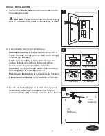
Page 7: ...uded Angle style mounting is best suited for angled or vaulted ceilings A longer downrod is sometimes necessary to ensure proper blade clearance Important If using the angle mount check to ensure the...

Page 8: ...installing the mounting bracket D as this will support the fan Important If using the angle mount ensure the open end of the mounting bracket D is installed facing the higher point of the ceiling 5 Re...

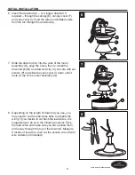
Page 9: ...nd downrod clip C Secure with set screws P and slide the yoke cover I down until it rests on top of the motor assembly G 8 Depending on the length of downrod you use you may need to cut the lead wires...

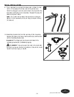
Page 10: ...you did not cut back the lead wires in Step 8 Step 9 is not necessary and you may proceed to Step 10 instead 10 Install the downrod A into the opening of the mounting bracket D Align one slot in the...

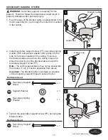
Page 11: ...p of the braided cable around the secondary support screw FF Note The ceiling support brace may not be accessible from below If not it must be accessed from above Important The braided cable must make...

Page 12: ...tral supply wire Connect the Black and Blue wires from the fan to the Black hot supply wire Secure all wiring connections together with wire connectors AA Important The Blue fan wire is power for the...

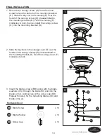
Page 13: ...y screw O into the mounting bracket D 2 Slide the key slots in the canopy cover F over the heads of the canopy screws O preassembled to the mounting bracket D Twist the canopy cover F clockwise to loc...

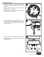
Page 14: ...ote The slot in the light kit H allows access to the preassembled motor screws N 5 Attach a blade assembly to the underside of motor assembly G using previously removed motor screws N Completely secur...

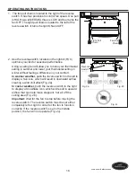
Page 15: ...into place once installed properly 8 Attach pull chain extensions EE to the pull chains Note When facing the reverse switch on the light kit H the fan pull chain is on the right and the light pull ch...

Page 16: ...t feeling a difference in your comfort In warmer weather push the reverse switch to the left to display a Sun icon which will result in downward airflow creating a wind chill effect Fig 2a In cooler w...

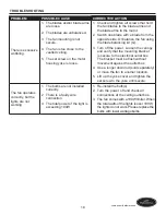
Page 17: ...ection 3 The plugs are not connected properly 4 The reverse switch is not completely engaged 1 Turn the power on or check the fuse 2 Turn the power off Loosen the canopy and check all connections 3 Ch...

Page 18: ...osen the canopy and verify that the mounting bracket is secure to the electrical outlet box The bracket must be flush without movement against the outlet box 4 Use a longer downrod sold separately or...

Page 19: ...alid Due to varying climate conditions this warranty does not cover any changes in brass finish including rusting pitting corroding tarnishing or peeling Brass finishes of this type give their longest...

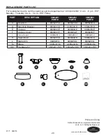
Page 20: ...T DESCRIPTION 0806201 PART 0806202 PART 0806203 PART A Downrod 0806201 A 0806202 A 0806203 A D Mounting Bracket 0806201 D 0806202 D 0806203 D E Canopy 0806201 E 0806202 E 0806203 E F Canopy Cover 0806...

Reviews: