background image

6

SAFETY INFORMATION

CAUTION:

 Read all instructions and safety information before installing your new fan. Review the 

accompanying assembly diagrams.

CAUTION:

 Be sure the outlet box is properly grounded or that a ground (green or bare) wire is present.

CAUTION:

 Carefully check all screws, bolts and nuts on the fan motor assembly to ensure they are 

secured.

CAUTION: This equipment has been tested and found to comply with the limits for a Class B digital 

device, pursuant to Part 15 of the FCC Rules. These limits are designed to provide reasonable 

protection against harmful interference in a residential installation. This equipment generates, 

uses and can radiate radio frequency energy and, if not installed and used in accordance with 

the instructions, may cause harmful interference to radio communications. However, there is no 

guarantee that interference will not occur in a particular installation. If this equipment does cause 

harmful interference to radio or television reception, which can be determined by turning the 

equipment off and on, the user is encouraged to try to correct the interference by one or more of the 

following measures:

--Reorient or relocate the receiving antenna.

--Increase the separation between the equipment and receiver

--Connect the equipment into and outlet on a circuit different from that to which the receiver is 

connected.

--Consult the dealer or an experienced radio/TV technician for help.

Please note changes or modifications not expressly approved by the party responsible for compliance 

could void the user’s authority to operate the equipment.

PREPARATION

Before beginning the assembly of this product, ensure that all parts are present. Compare all parts 

with the package contents list and hardware contents list. If any part is missing or damaged, do not 

attempt to assemble the product.
After opening the top of the carton, remove the mounting hardware package from the foam inserts, 

then remove the motor assembly from the packaging and place it on a soft surface, such as a carpet, 

to avoid damage to the finish.

Estimated Assembly Time:

 120 minutes

Tools Required for Assembly (not included): Electrical Tape, Phillips Screwdriver, Pliers, Safety 

Glasses, Step Ladder, Wire Cutters and Wire Strippers
Helpful Tools (not included): AC Tester Light, Tape Measure and Wiring Handbook

Summary of Contents for 40680

Page 1: ...nt at 1 800 643 0067 8 a m 6 p m EST Monday Thursday 8 a m 5 p m EST Friday ATTACH YOUR RECEIPT HERE Purchase Date _________________________ Harbor Breeze is a registered trademark of LF LLC All Right...

Page 2: ...3 Hardware Contents 4 Safety Information 5 Preparation 6 Initial Installation 7 Wiring 9 Final Installation 10 Operating Instructions 13 Care and Maintenance 14 Troubleshooting 14 Limited Lifetime Wa...

Page 3: ...h Housing D 1 F Motor Housing 1 G Blade Arm 4 H Blade 4 I Glass Globe 1 J Bulb 1 K Lower Bracket Screw preassembled to Lower Mounting Bracket B 1 L Thumbscrew preassembled to Light Kit E 3 M Motor Scr...

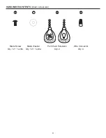
Page 4: ...4 HARDWARE CONTENTS shown actual size Blade Screw Qty 12 1 extra Blade Washer Qty 12 1 extra Pull Chain Extension Qty 2 Wire Connector Qty 4 AA BB CC DD H arbor Bree z e H arbor Bree z e...

Page 5: ...ersonal injury mount the fan to an oulet box marked ACCEPTABLE FOR FAN SUPPORT and use the mounting screws provided with the outlet box Most outlet boxes commonly used for the support of lighting fixt...

Page 6: ...is encouraged to try to correct the interference by one or more of the following measures Reorient or relocate the receiving antenna Increase the separation between the equipment and receiver Connect...

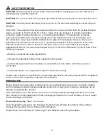
Page 7: ...allation may result in serious injury or death 2 This fan is intended for Flushmount installations Standard Mounting Angled Mounting and Closemount installations are not available 2 Standard Mounting...

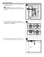
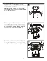
Page 8: ...it will support the fan 4 5 Remove the preassembled lower bracket screw K from the lower mounting bracket B and the upper bracket screws P from the upper mounting bracket A Insert the tab of the lower...

Page 9: ...her with wire connectors DD Note If there is a second hot power wire coming from the outlet box connect it to the blue light power fan wire for separate light and fan control Note The Black wire is ho...

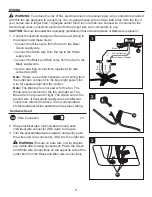
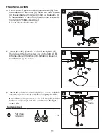
Page 10: ...ousing F over the motor C aligning the slotted holes in the motor housing F with the loosened motor housing screws N in the upper mounting bracket A Twist the motor housing F to lock then re insert th...

Page 11: ...light kit E Then loosen the thumbscrews L on the light kit E Lift glass globe I to light kit E tightening loosened thumbscrews L to secure 6 Attach the pull chain extensions CC or custom pull chain e...

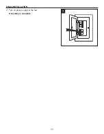
Page 12: ...12 FINAL INSTALLATION 7 Turn on power supply to the fan Assembly is complete 7...

Page 13: ...ence in your comfort Note Wait for the fan to stop before moving the reverse switch 2a In warmer weather push the reverse switch down to display a sun icon which will result in downward airflow creati...

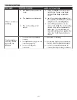
Page 14: ...everse switch is not engaged 2 The wall switch is turned off 3 The power is off or the fuse breaker is blown 4 There is a faulty wire connection 1 Firmly push the reverse switch completely up or down...

Page 15: ...ncing kit O 3 Turn off the power Loosen the canopy and verify that the mounting bracket is secure to the electrical outlet box The bracket must be flush without movement against the outlet box Verify...

Page 16: ...arying climate conditions this warranty does not cover any changes in brass finish including rusting pitting corroding tarnishing or peeling Brass finishes of this type give their longest useful life...

Page 17: ...department at 1 800 643 0067 8 a m 6 p m EST Monday Thursday 8 a m 5 p m EST Friday A C D E F G PART DESCRIPTION PART A Upper Mounting Bracket 807431 A F Motor Housing 807431 F G Blade Arm 807431 G H...

Reviews: