background image

5

PREPARATION

HARDWARE CONTENTS 

(shown actual size)

Before beginning assembly of product, make sure all parts are present. Place motor on carpet or on 
foam to avoid damage to 

fi

nish. Compare parts with package contents list and hardware contents list. If 

any part is missing or damaged, do not attempt to install, operate or assemble the product.

Estimated Assembly Time: 120 minutes

Tools Required for Assembly (not included): Electrical Tape, Phillips Screwdriver, Pliers, Safety Glasses, 
Stepladder and Wire Strippers.

Helpful Tools (not included):

AC Tester Light, Tape Measure, Do-It-Yourself Wiring Handbook and Wire 

Cutters.

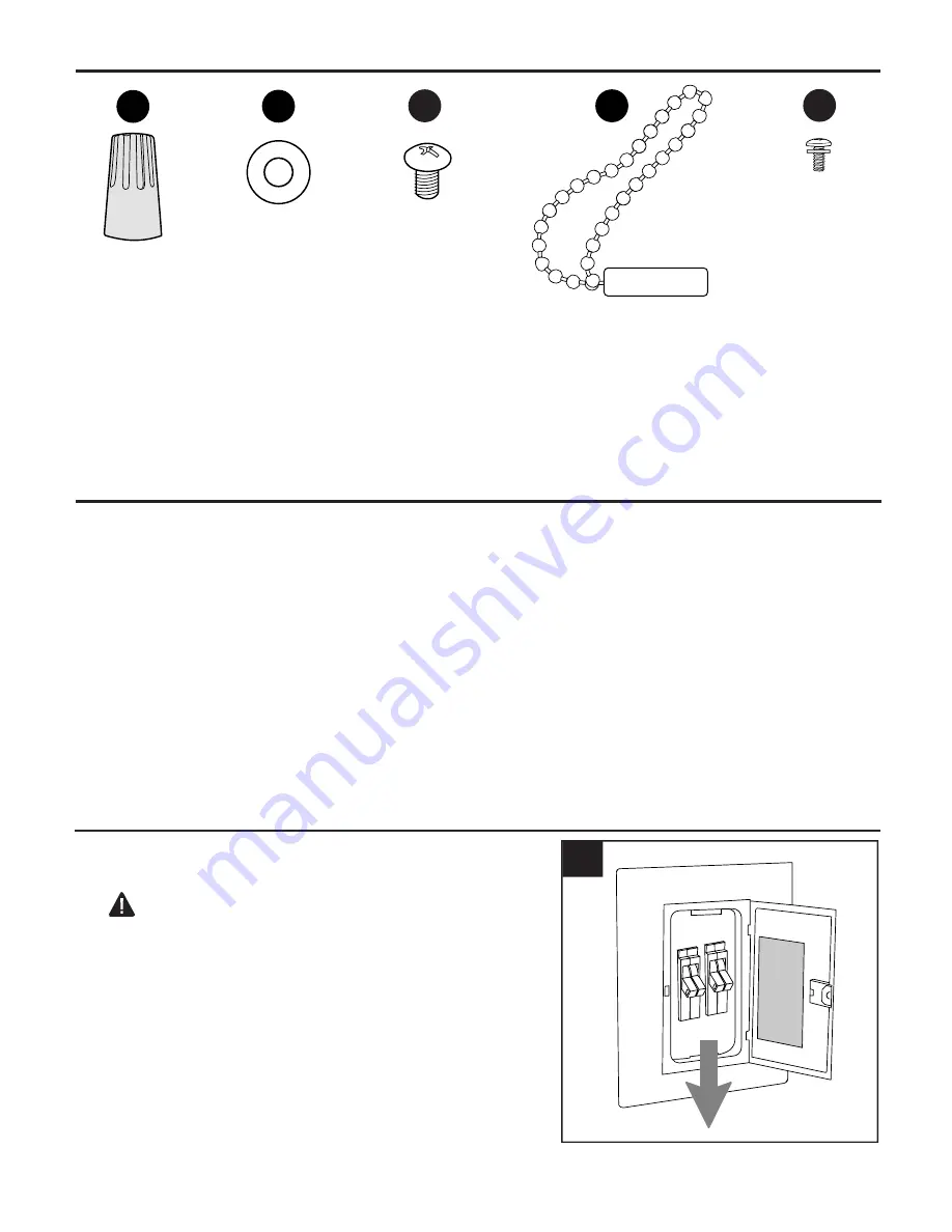
Wire

Connector

Qty. 4

AA

BB

Blade

Screw

Qty. 9

+ 1 extra

CC

INITIAL INSTALLATION

Turn off circuit breakers or fuse and wall switch to 
the fan supply line leads. 


DANGER:

 Failure to disconnect power supply 

prior to installation may result in serious injury or 
death.

 1.

ON

OFF

ON

OFF

1

Fiber

Blade

Washer

Qty. 9

+ 1 extra

Pull Chain 

Extension

Qty. 1

DD

EE

Screw

/Lock Washer

Qty. 1 extra

Summary of Contents for BOD52MW3

Page 1: ...R BREEZE and logo design are trademarks or registered trademarks of LF LLC All rights reserved Questions problems missing parts Before returning to your retailer call our customer service department a...

Page 2: ...on After you install the fan make sure all connections are secure to prevent the fan from falling The net weight of this fan is 13 23 lbs Distributed by Lowe s Home Centers LLC 1000 Lowe s Blvd Moores...

Page 3: ...larger than 12 gauge or there is more than one house wire to connect to the corresponding fan lead wires consult an electrician for the proper size wire connectors to use To reduce the risk of fire o...

Page 4: ...ket 1 D Motor Housing 1 E Yoke Cover 1 F Switch Housing 1 G Blade Arm 3 H Blade 3 DESCRIPTION PART QUANTITY PACKAGE CONTENTS E DESCRIPTION PART QUANTITY I Canopy Cover 1 J Canopy Mounting Screw 2 prea...

Page 5: ...or Assembly not included Electrical Tape Phillips Screwdriver Pliers Safety Glasses Stepladder and Wire Strippers Helpful Tools not included AC Tester Light Tape Measure Do It Yourself Wiring Handbook...

Page 6: ...clearance 6 Check to make sure blades H will be at least 30 inches from any obstruction Check downrod A length to ensure blades H will be at least 7 ft above the floor 3 INITIAL INSTALLATION 7 ft min...

Page 7: ...ade washers BB into holes in blade H to attach blade arm G to blade H Then tighten each blade screw CC starting with the one in the middle Repeat Step 6 for remaining blades H and blade arms G 6 Fiber...

Page 8: ...motor screw holes on the underside of the motor housing D Secure the top and bottom of the blade arm G to the motor housing D with previously removed motor screws lock washers N Steps 5a 5b page 7 Tig...

Page 9: ...ll on the downrod and measure 8 in of lead wire then cut the excess wire off with wire cutters not included NOTE If you do not cut back the lead wires Steps 11 and 12 are not necessary and you may pro...

Page 10: ...e slot in the ball with the tab may result in serious injury or death Tab 13 C Slot If you decided to cut back the lead wires in Step 11 strip 3 4 in of insulation from end of each wire white black gr...

Page 11: ...he remote control before proceeding with these wiring instructions For each wire connection below use one of the wire connectors AA provided making sure to screw wire connector AA on in a clockwise di...

Page 12: ...switch housing screws M from switch housing plate on underside of motor housing D Connect male plug from motor housing D to female plug from switch housing F matching up the colors on the male plug w...

Page 13: ...an for seasonal performance A ceiling fan will allow you to raise your thermostat setting in summer and lower your thermostat setting in winter without feeling a difference in your comfort NOTE Wait f...

Page 14: ...switch in the RIGHT position will result in upward airflow that can help move stagnant hot air off the ceiling area CARE AND MAINTENANCE At least twice each year lower canopy B to check downrod A asse...

Page 15: ...ace with an approved speed control device 4 Allow fan a break in period of a few days especially when running the fan at Medium and High speeds Excessive wobbling 1 Blades are loose 2 Blade arms incor...

Page 16: ...uring the limited lifetime warranty Any service performed by an unauthorized person will render the warranty invalid Due to varying climatic conditions this warranty does not cover changes in brass fi...

Page 17: ...los derechos reservados APTO PARA USO EN LUGARES H MEDOS Preguntas problemas piezas faltantes Antes de volver a la tienda llame a nuestro Departamento de Servicio al Cliente al 1 888 251 1003 de lunes...

Page 18: ...ificado o consulte un manual de cableado para hacerlo usted mismo Aseg rese de que en el lugar de instalaci n que elija se pueda establecer una distancia m nima de 2 13 m desde las aspas hasta el piso...

Page 19: ...nectar a los cables conductores del ventilador correspondientes consulte a un electricista cu l es el tama o adecuado de los conectores de cables que debe utilizar Para reducir el riesgo de incendios...

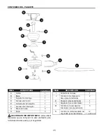
Page 20: ...D Carcasa del motor 1 E Cubierta de la horquilla 1 F Carcasa del interruptor 1 G Brazo del aspa 3 H Aspa 3 DESCRIPCI N PIEZA CANTIDAD I Cubierta de la base 1 J Tornillo de montaje de la 2 base preensa...

Page 21: ...ar ni ensamblar el producto si falta alguna pieza o si est n da adas Tiempo estimado de ensamblaje 120 minutos Herramientas necesarias para el ensamblaje no se incluyen cinta aislante destornillador P...

Page 22: ...e las aspas 22 Compruebe que las aspas H estar n al menos a 76 2 cm de cualquier obst culo Verifique el largo de la varilla A para asegurarse de que las aspas H estar n al menos a 2 13 m por encima de...

Page 23: ...del aspa G al aspa H Luego apriete cada uno de los tornillos para las aspas CC comenzando por el que est en el centro Repita el Paso 6 para las aspas H y los brazos del aspa G restantes 6 6 BB CC G Re...

Page 24: ...r D Fije la parte superior y la inferior del brazo del aspa G a la carcasa del motor D con los tornillos del motor arandelas de seguridad N que retir anteriormente Pasos 5a y 5b p gina 23 Apriete los...

Page 25: ...cm Tornillo de fijaci n y tuerca Vista lateral Dependiendo del largo de la varilla que utilice es posible que necesite cortar los cables conductores para simplificar el cableado Si decide cortar los c...

Page 26: ...ura de la bola con la leng eta podr an producirse lesiones graves o la muerte 13 C Si decidi acortar los cables conductores en el Paso 11 pele 1 91 cm del aislamiento del extremo de cada cable blanco...

Page 27: ...de un cable para conectar a los cables conductores del ventilador correspondientes consulte a un electricista cu l es el tama o adecuado de los conectores de cables que debe utilizar PRECAUCI N aseg...

Page 28: ...r ADVERTENCIA RIESGO DE DESCARGA No se debe retirar el pl stico que une las conexiones molex dentro de la carcasa del interruptor F Las conexiones molex no se deben utilizar a menos que instale el kit...

Page 29: ...er el interruptor de reversa 2 La cadena de tiro ubicada en la carcasa del interruptor F tiene cuatro posiciones para controlar la velocidad del ventilador Jale una vez para la posici n HIGH alta dos...

Page 30: ...electricidad No utilice agua ni un pa o h medo para limpiar el ventilador de techo INSTRUCCIONES DE FUNCIONAMIENTO 3c IMPORTANTE el interruptor de reversa se debe configurar ya sea completamente HACI...

Page 31: ...s 2 Reemplace el aspa 3 Use solo el dispositivo de control de velocidad que se incluye 4 Permita que el ventilador tenga un per odo de asentamiento de un par de d as especialmente cuando el ventilador...

Page 32: ...si n o descascarado Los ventiladores con acabado de lat n mantienen su belleza cuando se los protege de las condiciones clim ticas cambiantes La garant a no cubre los elementos de vidrio incluidos con...

Reviews: