8
INITIAL INSTALLATION
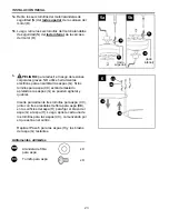
Remove pin (K) and clip (L) from downrod (A).
Partially loosen preassembled set screws and nut in
motor housing yoke at top of motor housing (D).
8a.
8a
K
L
8b
A
Set Screw
Sideview
D
Yoke
8b.
D
7
G
N
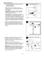
Align top of blade arm (G) (labeled
THIS SIDE UP
)
with two motor screw holes on topside of motor
housing (D) while allowing the bottom of the blade arm
(G) to align with the two corresponding motor screw
holes on the underside of the motor housing (D).
Secure the top and bottom of the blade arm (G) to the
motor housing (D) with previously removed motor
screws/lock washers (N) (Steps 5a & 5b, page 7).
Tighten motor screws/lock washers (N) securely.
Repeat Step 7 for remaining blade arms (G).
NOTE:
Make sure to completely secure each blade
arm (G) before proceeding to the next.
7.
N
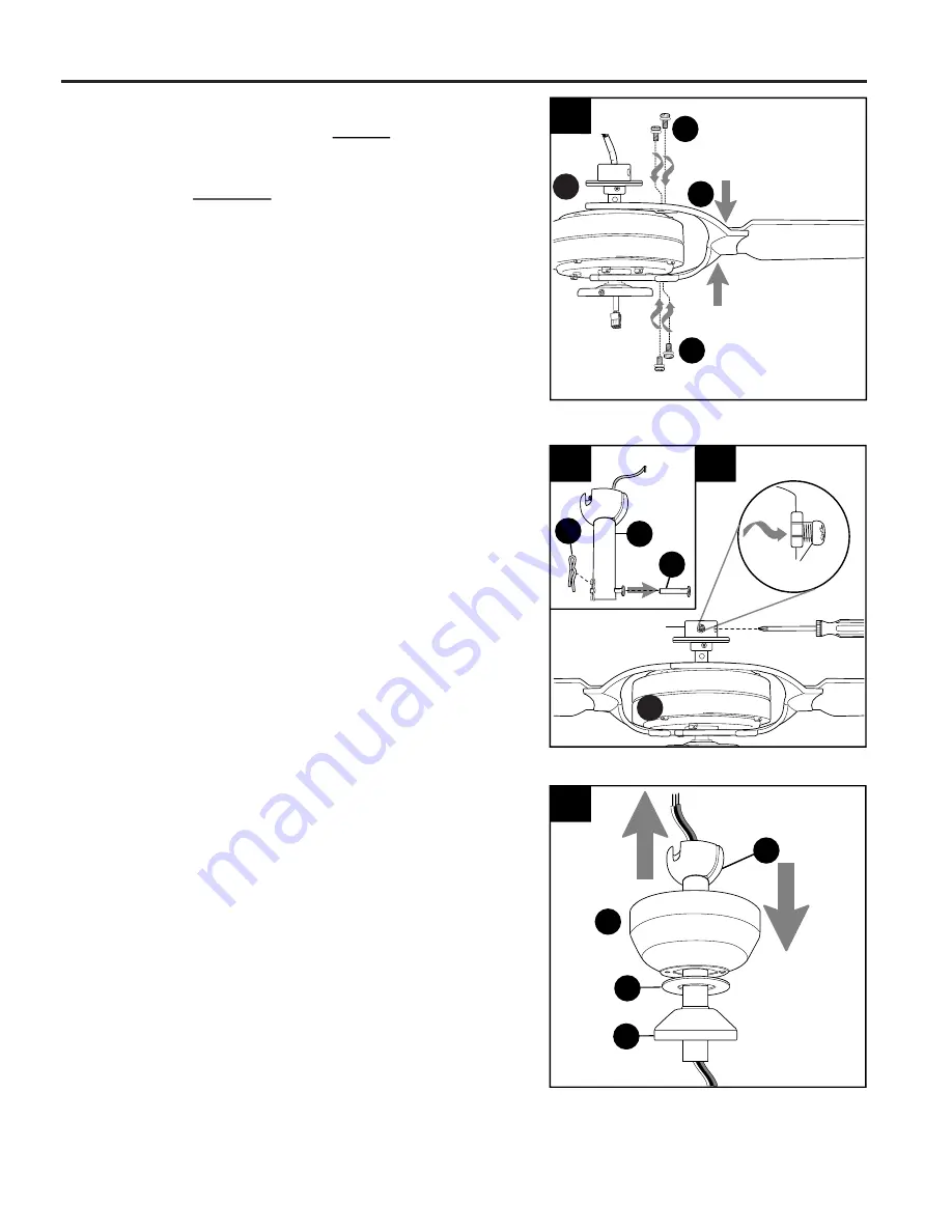
9. Insert downrod (A) through canopy (B), canopy cover
(I) and yoke cover (E).
NOTE:
Canopy cover (I) must
be turned with the smooth side TOWARD the motor
housing (D).
Then, thread wires from motor housing (D) through
downrod (A).
B
E
A
I
9
Yoke
D


