background image

BRADBURY CEILING FAN

ITEM #1597000

1596999

MODEL 

#

BRD48BNK6LRS
BRD60BNK6LRS

Questions, problems, missing parts?

 Before returning to your retailer, call our customer 

service department at 

1-800-527-1292

, 8:30 a.m. - 5 p.m., CST, Monday - Friday.

ATTACH YOUR RECEIPT HERE

Purchase Date

1

Español p. 22

4007498

ATTACH YOUR RECEIPT HERE

ADJUNTE SU RECIBO AQUÍ

Summary of Contents for BRADBURY BRD48BNK6LRS

Page 1: ...6LRS Questions problems missing parts Before returning to your retailer call our customer service department at 1 800 527 1292 8 30 a m 5 p m CST Monday Friday ATTACH YOUR RECEIPT HERE Purchase Date 1...

Page 2: ...ay cause harmful interference to radio communications However there is no guarantee that interference will not occur in a particular installation If this equipment does cause harmful interference to r...

Page 3: ...mounting screws provided with the outlet box Most outlet boxes commonly used for the support of lighting fixtures are not acceptable for fan support and may need to be replaced Consult a qualified el...

Page 4: ...If any servicing is required call our customer service department WARNING To reduce the risk of fire or electrical shock do not use the fan with any solid state speed control device or control fan spe...

Page 5: ...Yoke Cover 1 F LED Light Kit 1 G Blade 6 H Fitter Plate 1 I Shade 1 J Blade Arm 6 DESCRIPTION PART QUANTITY PACKAGE CONTENTS 5 E N O DESCRIPTION PART QUANTITY K Canopy Mounting Screw 4 Lock Washer pre...

Page 6: ...equired for Assembly not included Electrical Tape Phillips Screwdriver Pliers Safety Glasses Stepladder and Wire Strippers Helpful Tools not included AC Tester Light Tape Measure Do It Yourself Wiring...

Page 7: ...t to use a longer downrod not included Angle style mounting is best suited for angled or vaulted ceilings A longer downrod is sometimes necessary to ensure proper blade clearance 7 ft min 30 in min 3...

Page 8: ...STYLE FAN MOUNTING skip to page 10 DOWNROD STYLE FAN MOUNTING Remove pin L and clip M from downrod A Partially loosen preassembled set screws and nut in motor housing yoke at top of motor housing D 1...

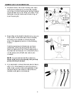
Page 9: ...ad wires it is suggested you do so in the following manner Take the lead wires and make sure you have pulled them all the way through the top of the downrod Start at the TOP of the hanging ball on the...

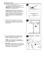
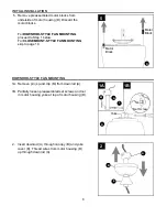
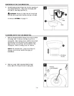
Page 10: ...OUNT STYLE FAN MOUNTING Remove preassembled canopy cover from bottom of canopy B To remove canopy cover from canopy B twist canopy cover until the two small protrusions on the inner lip of the canopy...

Page 11: ...house wires are different colors than referred to in the following steps stop immediately A professional electrician is recommended to determine wiring WARNING Using a full range dimmer switch not in...

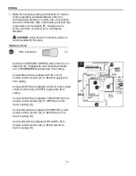
Page 12: ...g Connect BLACK wire labeled AC IN L from remote control receiver Q to BLACK supply wire from ceiling Connect WHITE wire labeled AC IN N from remote control receiver Q to WHITE supply wire from ceilin...

Page 13: ...remote control receiver Q flat side up into mounting bracket C Turn spliced taped wires upward and gently push wires and wire connectors CC into outlet box Let antenna from remote control receiver Q h...

Page 14: ...shers K securely 1 B K 1 2 DANGER To reduce the risk of serious bodily injury DO NOT use power tools to assemble the blades G If screws are overtightened blades G may crack and break Partially insert...

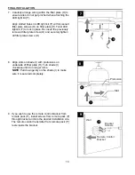
Page 15: ...ed and securely tighten all three motor plate screws N 4 Motor Plate Molex Connections I H D 5 Partially loosen two fitter plate screws O on the underside of the fitter plate H and remove the other fi...

Page 16: ...ly tighten all fitter plate screws O 8 Align slots on shade I with protrusions on underside of fitter plate H Turn shade I clockwise until it no longer turns NOTE Pull down gently on the shade I to ma...

Page 17: ...rence by one or more of the following measures Reorient or relocate the receiving antenna Increase the separation between the equipment and receiver Connect the equipment into an outlet on a circuit d...

Page 18: ...HIGH speed 2 button for fan MEDIUM speed 1 button for fan LOW speed 0 button to turn fan OFF button to turn light ON or OFF Tap button quickly to turn lights off or on Hold button down to increase or...

Page 19: ...ll result in upward airflow that can help move stagnant hot air off the ceiling area At least twice each year lower canopy B to check downrod A assembly and tighten all screws on fan Clean motor housi...

Page 20: ...ose 2 Unbalanced blades 3 Fan not securely mounted 4 Fan too close to vaulted ceiling 5 Set screw s on motor housing yoke is are not tightened properly 6 Set screw on hanging ball is not tightened pro...

Page 21: ...nditions Any glass provided with this fan is not covered by the warranty Any replacement of defective parts for the ceiling fan must be reported within the first year from the date of purchase For the...

Page 22: ...NK6LRS BRD60BNK6LRS Preguntas problemas piezas faltantes Antes de volver a la tienda llame a nuestro Departamento de Servicio al Cliente al 1 800 527 1292 de lunes a viernes de 8 30 a m a 5 p m hora e...

Page 23: ...se instala y se usa de acuerdo con las instrucciones puede causar interferencia perjudicial a las comunicaciones de radio Sin embargo no se garantiza que no se producir n interferencias en una instal...

Page 24: ...ontaje que se proporcionan con la caja de salida La mayor a de las cajas de salida que se usan com nmente para sostener l mparas no son aptas para sostener un ventilador y puede ser necesario reemplaz...

Page 25: ...nuestro Departamento de Servicio al Cliente ADVERTENCIA Para reducir el riesgo de incendios o descargas el ctricas no use el ventilador con dispositivos de control de velocidad para ventiladores de es...

Page 26: ...1 G Aspa 6 H Placa de soporte 1 I Pantalla 1 J Brazo del aspa 6 DESCRIPCI N PIEZA CANTIDAD CONTENIDO DEL PAQUETE 26 DESCRIPCI N PIEZA CANTIDAD K Tornillo de montaje de la base 4 arandela de seguriad p...

Page 27: ...te destornillador Phillips pinzas gafas de seguridad escalera de tijera y pelacables Herramientas tiles no se incluyen luz de prueba de CA cinta m trica manual de cableado H galo usted mismo y pinzas...

Page 28: ...os techos en ngulo o de b veda En ocasiones es necesaria una varilla m s larga para asegurar el espacio libre de las aspas INSTALACI N INICIAL G 4 Extremo abierto 4 C C MONTAJE EN NGULO MONTAJE EST ND...

Page 29: ...gina 31 Tope del motor MONTAJE DEL VENTILADOR EN ESTILO DE VARILLA Retire el pasador L y el sujetador M de la varilla A Afloje parcialmente los tornillos de fijaci n y la tuerca preensamblados en la...

Page 30: ...es para simplificar el cableado Si decide cortar los cables conductores se sugiere hacerlo de la siguiente manera Tome los cables conductores y aseg rese de jalarlos completamente a trav s de la parte...

Page 31: ...base de la parte inferior de la base B Para retirar la cubierta de la base gire la cubierta de la base hasta que las dos protuberancias peque as en el borde interior de la cubierta de la base se aline...

Page 32: ...la casa es de un calibre superior a 12 o hay m s de un cable para conectar a los cables conductores del ventilador correspondientes consulte a un electricista cu l es el tama o adecuado de los conecto...

Page 33: ...r NEGRO marcado AC IN L desde el receptor del control remoto Q con el conductor de alimentaci n NEGRO del techo Conecte el conductor BLANCO marcado AC IN N desde el receptor del control remoto Q con e...

Page 34: ...o Q con el lado plano hacia arriba en el soporte de montaje C Gire los cables empalmados o cubiertos con cinta hacia arriba y empuje suavemente los cables y los conectores de cables CC hacia dentro de...

Page 35: ...dos tornillos de montaje de la base arandelas de seguridad K Ahora levante la base B hacia el soporte de montaje C nuevamente alineando los orificios ranurados en la base B con los tornillos de monta...

Page 36: ...emente los tres tornillos de la placa del motor N Placa del motor Conexiones molex 5 Afloje parcialmente dos tornillos de la placa de soporte O en la parte inferior de la placa de soporte H y retire e...

Page 37: ...e todos los tornillos de la placa de soporte O H 7 8 Alinee las ranuras de la pantalla I con las protuberancias en la parte inferior de la placa de soporte H Gire la pantalla I en direcci n de las man...

Page 38: ...as siguientes medidas Reorientar o reubicar la antena receptora Aumentar la separaci n entre el equipo y el receptor Conectar el equipo a una salida en un circuito diferente de aquel al que el recepto...

Page 39: ...n 2 para velocidad MEDIA del ventilador bot n 1 para velocidad BAJA del ventilador bot n 0 para el ventilador APAGAR bot n para las luces ENCENDER o o APAGAR Presione r pidamente el bot n para encende...

Page 40: ...o de aire ascendente que puede ayudar a mover el aire caliente estancado fuera del rea del techo Al menos dos veces al a o baje la base B para revisar el ensamble de la varilla A y apriete todos los t...

Page 41: ...ilibradas 3 El ventilador no est montado de manera segura 4 El ventilador est demasiado cerca del techo de b veda 5 Los tornillos de fijaci n en la horquilla de la carcasa del motor no est n bien apre...

Page 42: ...mbiantes La garant a no cubre los elementos de vidrio incluidos con este ventilador Cualquier reemplazo de piezas defectuosas para el ventilador de techo debe informarse dentro del primer a o a partir...

Reviews: