background image

11

Lowes.com/harborbreeze

WIRING

1c. 

FAN AND LIGHT CONTROLLED BY TWO 

WALL SWITCHES:

 Connect BLACK wire from fan 

to BLACK wire from the independent wall switch for 
the fan. Connect BLUE wire from fan to the BLACK 
wire from the other independent wall switch for the 
light. Connect WHITE wire from fan to WHITE wire 
from ceiling. Connect GROUND (GREEN) wires  
from downrod (A) and mounting bracket (C) to 
BARE/GREEN wire from ceiling.

NOTE:

 BLACK wire is hot power for fan. BLUE wire 

is hot power for light kit. WHITE wire is common for 
fan and light kit. GREEN or BARE wire is ground.

Wrap electrical tape (not included) around each 
individual wire connector (AA) down to the wire. 


WARNING

: Make sure no bare wire or wire 

strands are visible after making connections. Place 
GREEN and WHITE wire connections on the 
opposite side of the outlet box from the BLACK and 
BLUE wire connections.

Turn spliced/taped wires upward and gently push 
wires and wire connectors (AA) into outlet box.

 2. 

AA

E3 Wire Connector                                    x 4 

Hardware Used

AA

AA

2

AA

1b. 

FAN CONTROLLED BY PULL CHAIN, LIGHT 

BY WALL SWITCH:

 Connect BLACK wire from fan 

to BLACK wire from ceiling. Connect BLUE wire 
from fan to the BLACK wire from the independent 
wall switch for the light. Connect WHITE wire from 
fan to WHITE wire from ceiling. Connect GROUND 
(GREEN) wires from (downrod (A) and mounting 
bracket (C) to BARE/GREEN wire from ceiling.

FAN AND LIGHT CONTROLLED BY TWO WALL SWITCHES

FAN CONTROLLED BY PULL CHAIN, LIGHT BY WALL SWITCH

BLACK

BLACK
(WALL
SWITCH)

BLUE

1b

WHITE

BLACK (POWER)

WHITE (NEUTRAL) 

GROUND/GREEN (BARE)

BLACK

FAN AND LIGHT CONTROLLED BY TWO WALL SWITCHES

FAN AND LIGHT CONTROLLED BY TWO WALL SWITCHES

BLACK

BLUE

1c

WHITE

BLACK (WALL SWITCH)

WHITE (NEUTRAL) 

GROUND/GREEN (BARE)

GREEN

120V POWER 
FROM CEILING

BLACK

BLACK
(WALL SWITCH
FOR LIGHT)

120V POWER 
FROM CEILING

GREEN

GREEN

GREEN

Summary of Contents for Cape Coast E-YLM52WW5C1

Page 1: ...M52WW5C1 Questions problems missing parts Before returning to your retailer call our customer service department at 1 800 643 0067 8 a m 6 p m EST Monday Thursday 8 a m 5 p m EST Friday ATTACH YOUR RE...

Page 2: ...the installation site you choose allows a minimum clearance of 7 ft from the blades to the floor and at least 30 in from the end of the blades to any obstruction After you install the fan make sure al...

Page 3: ...an electrician for the proper size wire connectors to use To reduce the risk of fire or electrical shock do not use the fan with any solid state speed control device or control fan speed with a full r...

Page 4: ...unting Screw 2 preassembled L Pin preassembled 1 M Clip preassembled 1 DESCRIPTION PART QUANTITY PACKAGE CONTENTS 4 Lowes com harborbreeze E N O P Q R S U DESCRIPTION PART QUANTITY N Hanging Ball Cove...

Page 5: ...or on foam to avoid damage to finish Compare parts with package contents list and hardware contents list If any part is missing or damaged do not attempt to install operate or assemble the product Est...

Page 6: ...F 1 Lowes com harborbreeze 2 Determine mounting method to use A Standard mount B Angle mount Note Flushmount and closemount options are not available for this fan IMPORTANT If using the angle mount en...

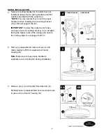
Page 7: ...e sure open end of mounting bracket C is installed facing the higher point of the ceiling and ensure the ceiling angle is not steeper than 19 4 5 Remove preassembled motor screws J and motor washers R...

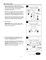
Page 8: ...If you do not cut back the lead wires Steps 9 and 10 are not necessary and you may proceed to Step 11 instead 9 8 INITIAL INSTALLATION Slip downrod A into motor housing yoke align holes and re instal...

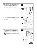
Page 9: ...m harborbreeze If you decided to cut back the lead wires in Step 9 strip 1 2 in of insulation from end of each wire white black green and blue if applicable Twist stripped ends of each strand of wire...

Page 10: ...our situation and make appropriate wiring connections as follows IMPORTANT Use one of the wire connectors AA provided to make each wire connection making sure to screw wire connector AA on in a clockw...

Page 11: ...the outlet box from the BLACK and BLUE wire connections Turn spliced taped wires upward and gently push wires and wire connectors AA into outlet box 2 AA E3 Wire Connector x 4 Hardware Used AA AA 2 AA...

Page 12: ...dges of blade screw posts T are captured by the recessed groove on the three C clips BB 2 Three C clip x 3 Hardware Used BB H BB G Friction Detents Recessed Groove 2 X T T BB 1 Locate two canopy mount...

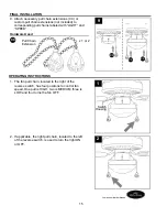
Page 13: ...eled FOR LIGHT and remove plastic from these two wires 4 FINAL INSTALLATION Lowes com harborbreeze 5 Remove hex nut O and lock washer P from the top of the threaded rod on light kit fitter F and locat...

Page 14: ...ten all switch housing screws S with a Phillips screwdriver 6 7 FINAL INSTALLATION Install bulbs Q IMPORTANT When you need to replace bulbs please allow the bulb s and glass shade to cool down before...

Page 15: ...If applicable the light pull chain located to the left of the reverse switch is used to turn the light ON or OFF OPERATING INSTRUCTIONS The fan pull chain located to the right of the reverse switch h...

Page 16: ...OT remove weatherproof cover on the reverse switch 3 OPERATING INSTRUCTIONS 3a 3b 3c 3c IMPORTANT Reverse switch must be set either completely UP or completely DOWN for fan to function If the reverse...

Page 17: ...unted 5 Fan too close to vaulted ceiling 6 Set screw s on motor housing yoke is are not tightened properly 7 Set screw on hanging ball is not tightened properly 1 Check Three C clips 2 Re install blad...

Page 18: ...this fan are the purchaser s own responsibility The distributor assumes no responsibility whatsoever for fan installation during the limited lifetime warranty Any service performed by an unauthorized...

Page 19: ...ina Harbor Breeze is a registered trademark of LF LLC All Rights Reserved Lowes com harborbreeze A Downrod B Canopy C Mounting Bracket F Light Kit Fitter G Blade H Blade Arm I Glass Shade U Switch Hou...

Page 20: ...problemas piezas faltantes Antes de volver a la tienda llame a nuestro Departamento de Servicio al Cliente al 1 800 643 0067 de lunes a jueves de 8 a m a 6 p m y los viernes de 8 a m a 5 p m hora est...

Page 21: ...i n que elija se pueda establecer una distancia m nima de 2 13 m desde las aspas hasta el piso y al menos 76 2 cm desde los extremos de las aspas hasta cualquier obst culo Una vez instalado el ventila...

Page 22: ...a un electricista cu l es el tama o adecuado de los conectores de cables que debe utilizar Para reducir el riesgo de incendios o descargas el ctricas no use el ventilador con dispositivos de control d...

Page 23: ...X Kit de equilibrio 1 RECORDATORIO IMPORTANTE Debe utilizar las piezas que se incluyen con este ventilador para la instalaci n adecuada y por seguridad A Varilla 1 B Base 1 C Soporte de montaje 1 D Ca...

Page 24: ...ma para evitar da ar el acabado Compare las piezas con la lista del contenido del paquete y la lista de aditamentos No intente instalar usar o ensamblar ni usar el producto si falta alguna pieza o si...

Page 25: ...com harborbreeze 2 Determine el m todo de instalaci n que utilizar A Montaje est ndar B Montaje en ngulo Nota Las opciones de montaje al ras y montaje cerrado no est n disponibles para este ventilado...

Page 26: ...direcci n hacia el punto m s alto del techo y aseg rese de que el ngulo del techo no tenga una inclinaci n superior a los 19 4 5 Retire los tornillos del motor J preensamblados y las arandelas del mo...

Page 27: ...el paso 11 en su lugar 9 8 INSTALACI N INICIAL Deslice la varilla A en la horquilla de la carcasa del motor alinee los orificios y vuelva a instalar el pasador L y el sujetador M Apriete los tornillo...

Page 28: ...eeze Si decidi cortar los cables conductores en el paso 9 pele 12 7 mm del aislamiento del extremo de cada cable blanco negro verde y azul si corresponde Tuerza los extremos pelados de cada filamento...

Page 29: ...u situaci n y realice las conexiones del cableado adecuadas como se indica a continuaci n IMPORTANTE Utilice uno de los conectores de cables AA provistos para realizar la conexi n de cada conductor y...

Page 30: ...uesto de la caja de salida con respecto a las conexiones del cableado NEGRA y AZUL Gire los cables empalmados o cubiertos con cinta hacia arriba y empuje suavemente los cables y los conectores de cabl...

Page 31: ...ada en los sujetadores triple C BB capturen los extremos de los postes de los tornillos para aspa T 1 2 Ubique dos tornillos de montaje de la base K debajo del soporte de montaje C y retire el tornill...

Page 32: ...os cables 4 INSTALACI N FINAL Lowes com harborbreeze 5 Retire la tuerca hexagonal O y la arandela de seguridad P de la varilla roscada en el soporte del kit de iluminaci n F y ubique el cable de puest...

Page 33: ...luego apriete todos los tornillos de la carcasa del interruptor S con un destornillador Phillips 6 7 INSTALACI N FINAL Instale las bombillas Q IMPORTANTE Cuando necesite reemplazar las bombillas deje...

Page 34: ...ubicada a la izquierda del interruptor de reversa se utiliza para ENCENDER o APAGAR la luz INSTRUCCIONES DE FUNCIONAMIENTO La cadena de tiro del ventilador ubicada a la derecha del interruptor de reve...

Page 35: ...UCCIONES DE FUNCIONAMIENTO 3c IMPORTANTE El interruptor de reversa se debe configurar ya sea completamente hacia ARRIBA o completamente hacia ABAJO para que funcione el ventilador Si el interruptor de...

Page 36: ...l ventilador no est bien montado 5 El ventilador est demasiado cerca del techo de b veda 6 Los tornillos de fijaci n en la horquilla de la carcasa del motor no est n bien apretados 7 El tornillo de fi...

Page 37: ...te ventilador o accesorios de fijaci n que no son del fabricante de este ventilador ser responsabilidad del comprador El distribuidor no asume ning n tipo de responsabilidad por la instalaci n del ven...

Page 38: ...so en China Harbor Breeze es una marca registrada de LF LLC Todos los derechos reservados Lowes com harborbreeze A B F C G A Varilla B Base C Soporte de montaje F Soporte del kit de iluminaci n G Aspa...

Reviews: