background image

Clip

Pin

F

A

E

F

A

Ball

9

ASSEMBLY INSTRUCTIONS

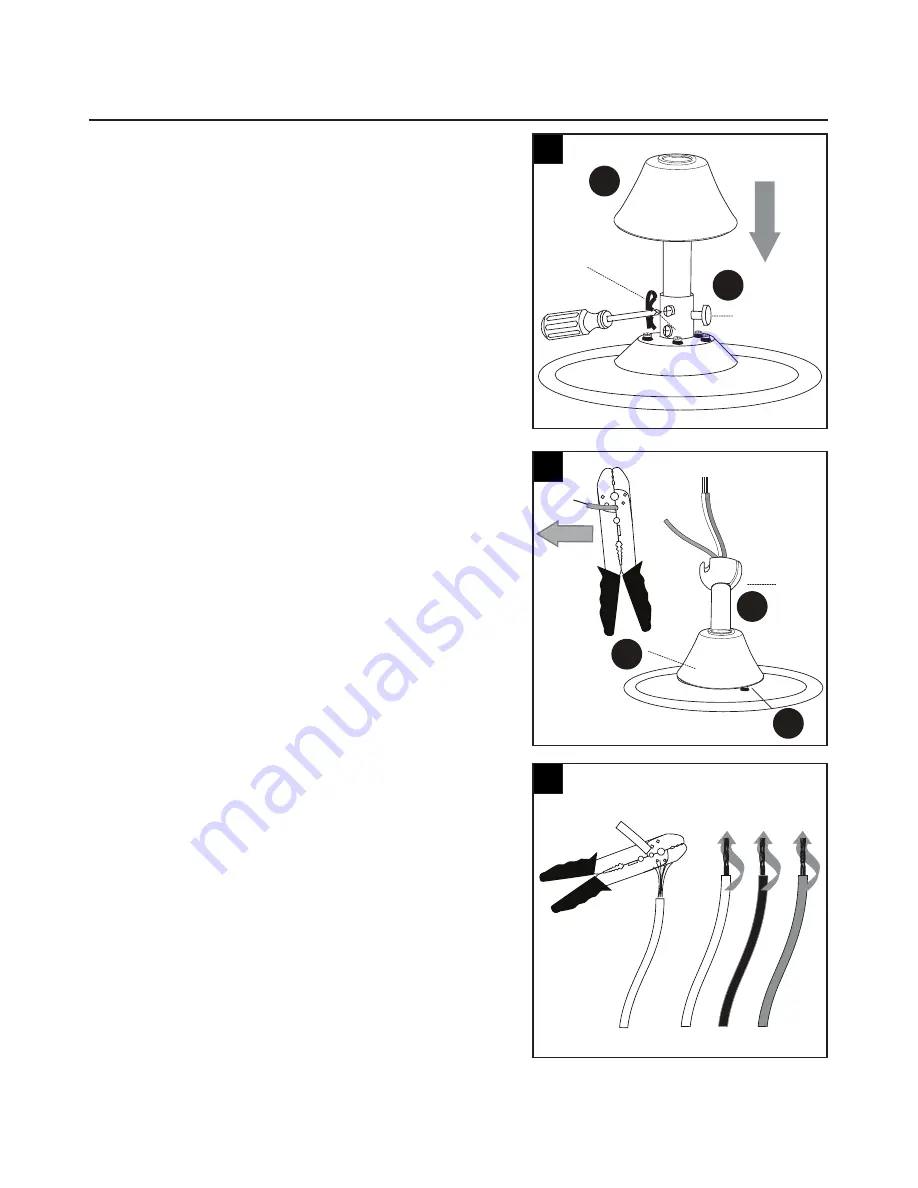
7. Slip downrod (A) into motor housing yoke, align holes 

and re-install pin and clip.  Re-tighten set screws in 
motor housing yoke and then tighten nuts.  Slide yoke 
cover (F) down until it rests on top of motor housing (E). 
[Fig. 7]

8. Depending on the length of downrod (A) you use, you 

may need to cut the lead wires back to simplify the 
wiring.  If you decide to cut back the lead wires, it is 
suggested that you do so in the following manner:  Take 
the lead wires and make sure that you have pulled 
them all the way through the top of the downrod (A) and 
measure 8 in. of lead wire, and then cut the excess wire 
off with wire cutters. [Fig. 8]

9. If you decided to cut back the lead wire in Step 9, 

strip 1/2 in. of insulation from end of white wire.
Twist stripped ends of each strand of wire within the 
insulation with pliers. [Fig. 10] Repeat Step 10 for 
black, blue (if applicable) and green wires.

Note

: If you did not cut back the lead wires, 

Step 10 

is not necessary and you may proceed to Step 11 
instead.

7

8

9

Summary of Contents for Casual-3-2011

Page 1: ...Breeze is a registered trademark of LF LLC All Rights Reserved ATTACH YOUR RECEIPT HERE Serial Number Purchase Date Questions problems missing parts Before returning to your retailer call our customer...

Page 2: ...3 Hardware Contents 4 Safety Information 5 Preparation 6 Assembly Instructions 7 Wiring 10 Final Installation 11 Operating Instructions 14 Care and Maintenance 16 Troubleshooting 16 Limited Lifetime W...

Page 3: ...A B C D E F G H I J PART K L M QUANTITY 1 1 1 1 1 1 5 5 1 2 QUANTITY 1 1 1 DESCRIPTION Downrod Canopy Mounting Bracket Light Kit Fitter Motor Assembly Yoke Cover Blade Arm Blade Glass Shade Bulb DESCR...

Page 4: ...4 HARDWARE CONTENTS shown actual size AA BB CC DD Motor Screw Qty 10 and 1 extra Blade Screw Qty 15 and 1 extra Blade Washer Qty 15 and 1 extra Wire Connector Qty 4...

Page 5: ...FWULF VKRFN GR 127 XVH D IXOO UDQJH GLPPHU VZLWFK to control DANGER When using an existing outlet box make sure the outlet box is securely attached to the building structure and can support the full w...

Page 6: ...wire is present After opening top of carton remove mounting hardware package from foam inserts Remove PRWRU IURP SDFNLQJ DQG SODFH RQ FDUSHW RU RQ IRDP WR DYRLG GDPDJH WR QLVK 2 CAUTION Carefully che...

Page 7: ...eck to make sure blades H will be at least 30 in from any obstructions Check downrod A length to HQVXUH EODGHV DUH DW OHDVW IW DERYH WKH RRU Fig 3 Important If using the angle mount check to make sure...

Page 8: ...g bracket C is installed facing the higher point of ceiling 5 Remove pin and clip from downrod A Partially loosen set screws in motor housing yoke at top of motor housing E Fig 5 Help Hint Downrod sty...

Page 9: ...ires it is suggested that you do so in the following manner Take the lead wires and make sure that you have pulled them all the way through the top of the downrod A and measure 8 in of lead wire and t...

Page 10: ...NING 7R UHGXFH WKH ULVN RI UH HOHFWULFDO VKRFN RU SHUVRQDO LQMXU ZLUH FRQQHFWRUV provided with this fan are designed to accept only one 12 guage house wire and two lead wires from the fan If your hous...

Page 11: ...ly into ceiling outlet box Remove one screw from the mounting bracket C and loosen the other screw around 1 4 in Align the canopy B up to ceiling and over the loose screw Place the canopy B into key h...

Page 12: ...g with the next step 4 Remove one of the four screws from the motor assembly E and loosen the other three Align the screw holes of the light kit plate L with the loosened screws and replace and tighte...

Page 13: ...please allow bulb J and light kit to cool down before touching the bulb J or the light kit Note fan uses two 13 watt max GU24 bi pin base CFL bulbs WARNING The CFL bulbs contain mercury discard then a...

Page 14: ...provides the function of multiplicative protection 1 Lock position The DC motor has a built in safety feature against obstruction during operation If this occurs the motor will discontinue operation w...

Page 15: ...uctions may cause harmful interference to radio communications However there is no guarantee that interference will not occur in a particular installation If this equipment does cause harmful interfer...

Page 16: ...d re start 5 The blade is overweight Don t install the unapproved blades 1 Tighten all blade screws 2 Replace blade 3 Replace with an approved speed control device 4 Allow fan a break in period of a f...

Page 17: ...the receipt as proof of purchase All costs of removing and reinstalling the product are your responsibility Any damage to any part such as by accident or PLVXVH RU LPSURSHU LQVWDOODWLRQ RU E DI LQJ D...

Page 18: ...0 13500104753100 13500104725100 13500104719200 DESCRIPTION Downrod Canopy Mounting Bracket Light Kit Fitter Yoke Cover Blade Arm Blade Glass Shade Canopy Cover Light Kit Plate Motor Screw Blade Screw...

Reviews: