
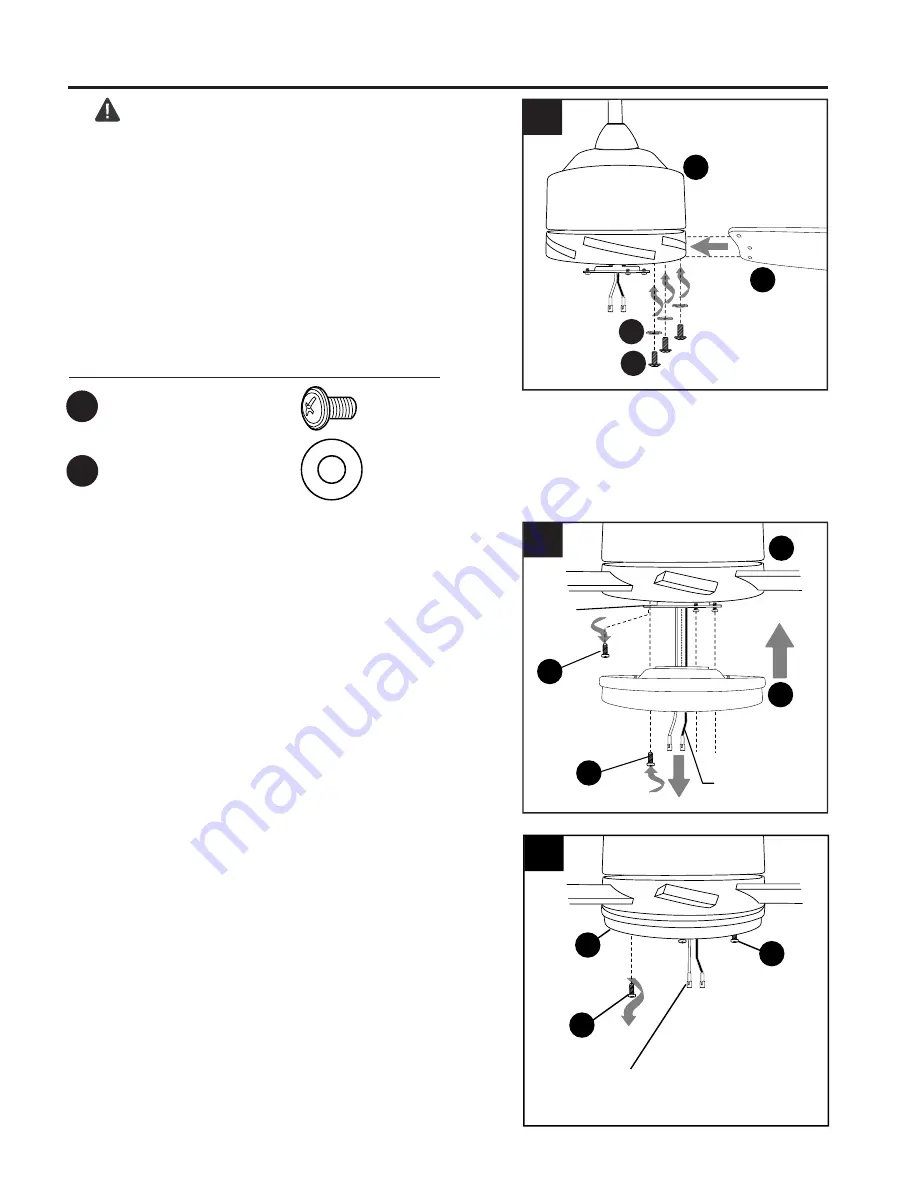
J
Molex
Connections
L
L
13
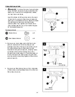
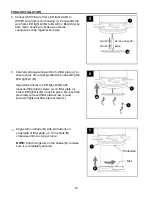
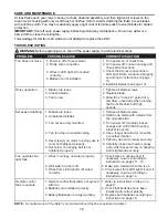
FINAL INSTALLATION
2.
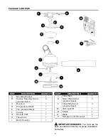
Hardware Used
AA
Blade Screw x 21
Fiber Blade Washer x 21
BB
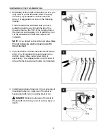
DANGER:
To reduce the risk of serious bodily
injury,
DO NOT use power tools to assemble the
blades (O). If screws are overtightened, blades
(O) may crack and break.
Insert the blade (O) through the slot on the band
of the motor housing (I). Align holes in blade (O)
with holes on underside of motor. Attach the blade
(O) with blade screws (AA) and fiber blade
washers (BB). Then, tighten each blade screw
(AA), starting with the one in the middle. Repeat
for remaining blades (O).
4.
3.
3
2
BB
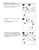
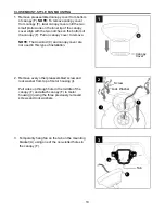
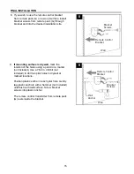
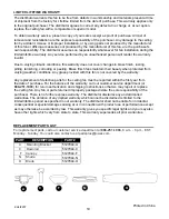
Remove one fitter plate screw (L) from underside
of fitter plate (J) and partially loosen the other two
fitter plate screws (L).
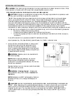
3
Motor
Plate
Molex
Connections
IO
I
4
IK
Remove one motor plate screw (K) from motor
plate on underside of motor housing (I) and
partially loosen the other two motor plate screws
(K). Align slotted holes in fitter plate (J) with
loosened motor plate screws (K), allowing molex
connections from motor housing (I) to come
through hole in fitter plate (J). Twist fitter plate (J)
to lock. Re-insert the motor plate screw (K) that
was removed and securely tighten all three motor
plate screws (K).
IK
IJ
AA
I


