18
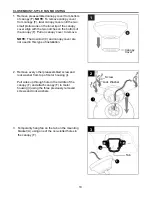
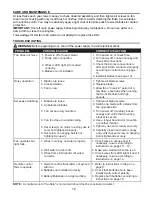
CARE AND MAINTENANCE
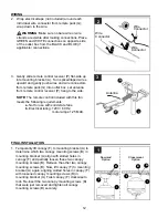
At least twice each year, lower canopy to check downrod assembly, and then tighten all screws on fan.
Clean motor housing with only a soft brush or lint-free cloth to avoid scratching the finish. Clean blades
with a lint-free cloth. You may occasionally apply a light coat of furniture polish to wood blades for added
protection.
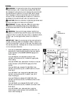
IMPORTANT:
Shut off main power supply before beginning any maintenance. Do not use water or a
damp cloth to clean the ceiling fan.
Total wattage for this fan is 20 watts; do not attempt to replace the LEDs.
WARNING:
Before beginning work, shut off the power supply to avoid electrical shock.
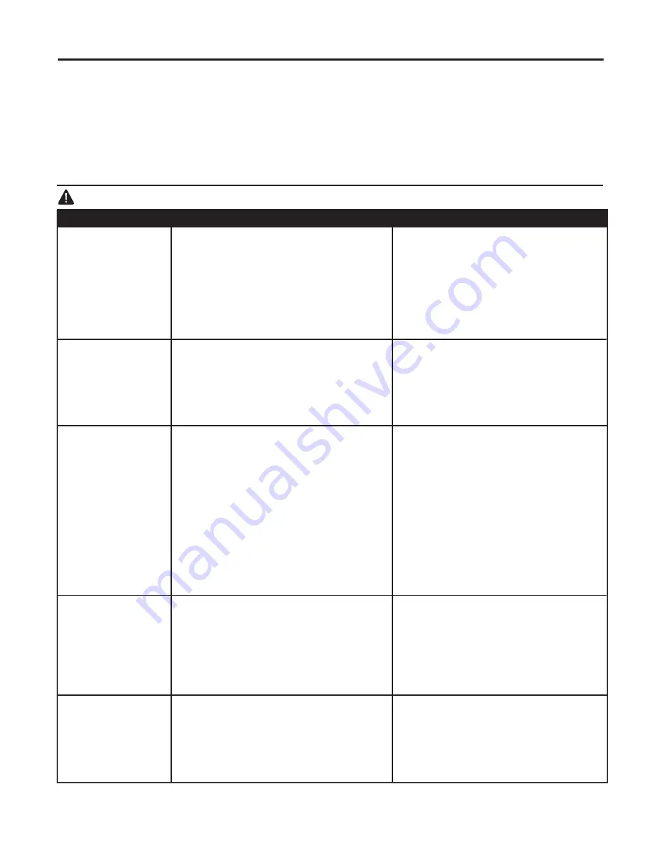
PROBLEM
POSSIBLE CAUSE
CORRECTIVE ACTION
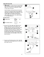
Fan does not move.
1. Power is off or fuse is blown.
2. Faulty wire connection.
3. Wires in LED light kit not wired
correctly.
4. Blades are not installed.
1. Turn power on or check fuse.
2. Turn power off. Loosen canopy and
check all connections.
3. Check that molex connections in
LED light kit are connected properly
according to instructions on page
14.
4. Install all blades (see page 13).
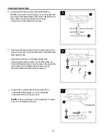
Noisy operation.
1. Blades are loose.
2. Cracked blade.
3. Fan is new.
1. Tighten all blade screws.
2. Replace blade.
3. Allow fan a “break in” period of a
few days, especially when running
the fan at Medium and High
speeds.
Excessive wobbling. 1. Blades are loose.
2. Unbalanced blades.
3. Fan not securely mounted.
4. Fan too close to vaulted ceiling.
5. Set screw(s) on motor housing yoke is
(are) not tightened properly.
6. Set screw on hanging ball is not
tightened properly.
1. Tighten all blade screws.
2. Switch one blade with a blade from
the opposite side.
3. Turn power off. Carefully loosen
canopy and verify that mounting
bracket is secure.
4. Use a longer downrod or move fan
to another location.
5. Tighten yoke set screw(s) securely.
6. Carefully loosen and lower canopy
and verify that set screw on hanging
ball is tightened securely.
TROUBLESHOOTING
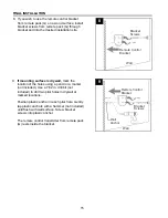
Fan operates but
light fails.
1. Wires in canopy not wired properly.
2. Wall switch to fan is off.
3. Wires from LED light kit not wired
correctly.
1. Check wires in canopy and, if
necessary, re-wire according to
instructions on pages 11 - 12.
2. Make sure wall switch to fan is on.
3. Check wires from LED light kit and, if
necessary, re-wire according to
instructions on page 14.
Remote control
fails to operate.
1. Remote control transmitter not synced
with fan.
2. Batteries not installed correctly.
3. Battery/Batteries no longer working.
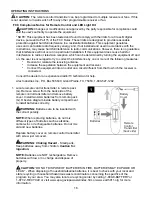
1. Refer to instructions in Step 2 on
page17.
2. Check that batteries have been
installed with correct polarity.
3. Replace both batteries according to
instructions on page 16.
NOTE:
A small amount of "wobble" is normal and should not be considered a defect.


