Printed in China
KHLI2207
19
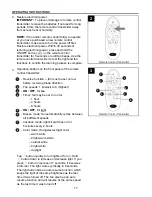
A
F
C
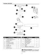
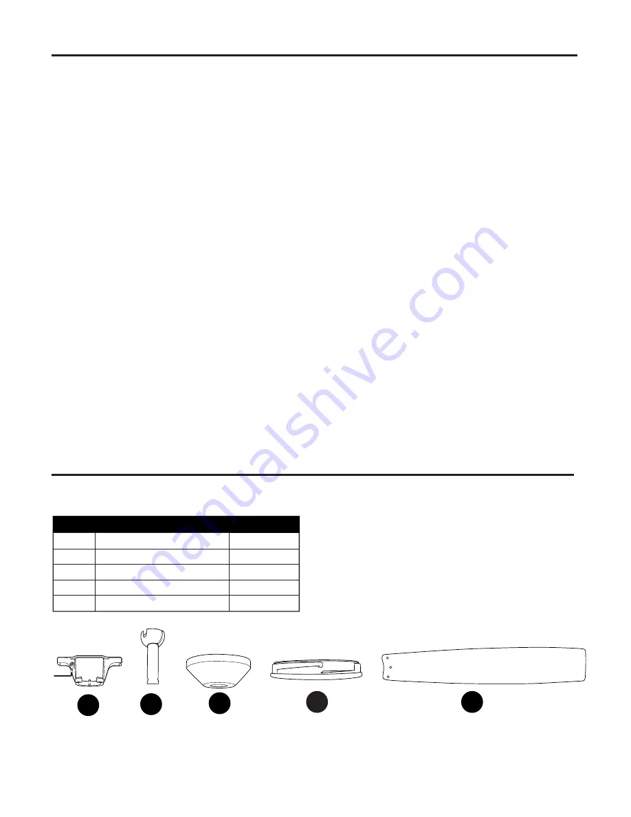
REPLACEMENT PARTS LIST
PART DESCRIPTION
A Mounting Bracket
C Downrod
F Canopy
N Shade
O Blade
5127844-A
5127844-C
5127844-F
5127844-N
5127844-O
PART #
For replacement parts, call our customer service department at
888-251-1003
, 8 a.m. - 8 p.m., EST,
Monday - Sunday. You could also contact us at partsplus@lowes.com.
N
O
LIMITED LIFETIME WARRANTY
The distributor warrants this fan to be free from defects in workmanship and materials present at time
of shipment from the factory for Lifetime limited from the date of purchase. This warranty applies only
to the original purchaser. The distributor agrees to correct any defect at no charge or, at our option,
replace the ceiling fan with a comparable or superior model.
To obtain warranty service, present a copy of your sales receipt as proof of purchase. All cost of
removal and reinstallation are the express responsibility of the purchaser. Any damage to the ceiling
fan by accident, misuse or improper installation, or by using parts not produced by the manufacturer
of this fan or affixing accessories not produced by the manufacturer of this fan, are the purchaser's
own responsibility. The distributor assumes no responsibility whatsoever for fan installation during the
limited lifetime warranty. Any service performed by an unauthorized person will render the warranty
invalid.
Due to varying climatic conditions, this warranty does not cover changes in brass finish, rusting,
pitting, tarnishing, corroding or peeling. Brass finish fans maintain their beauty when protected from
varying weather conditions. Any glass provided with this fan is not covered by the warranty.
Any replacement of defective parts for the ceiling fan must be reported within the first year from
the date of purchase. For the balance of the warranty, call our customer service department (
at
888-251-1003
)
for return authorization and shipping instructions so that we may repair or replace
the ceiling fan. Any fan or parts returned improperly packaged is/are the sole responsibility of the
purchaser. There is no further express warranty. The distributor disclaims any and all implied
warranties. The duration of any implied warranty which cannot be disclaimed is limited to the
limited lifetime period as specified in our warranty. The distributor shall not be liable for incidental,
consequential or special damages arising at or in connection with product use or performance except
as may otherwise be accorded by law. This warranty gives you specific legal rights and you may also
have other rights which vary from state to state. This warranty supersedes all prior warranties.


