background image

2

TABLE OF CONTENTS

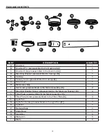
Package Contents  . . . . . . . . . . . . . . . . . . . . . . . . . . . . . . . . . . . . . . . . . . . . . . . . . . . . . . . . . . . . . . . . . 3

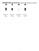
Hardware Contents  . . . . . . . . . . . . . . . . . . . . . . . . . . . . . . . . . . . . . . . . . . . . . . . . . . . . . . . . . . . . . . . . 4

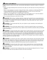
Safety Information  . . . . . . . . . . . . . . . . . . . . . . . . . . . . . . . . . . . . . . . . . . . . . . . . . . . . . . . . . . . . . . . . . 5

Preparation  . . . . . . . . . . . . . . . . . . . . . . . . . . . . . . . . . . . . . . . . . . . . . . . . . . . . . . . . . . . . . . . . . . . . . . 6

Initial Installation  . . . . . . . . . . . . . . . . . . . . . . . . . . . . . . . . . . . . . . . . . . . . . . . . . . . . . . . . . . . . . . . . . . 7

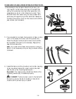
Standard or Angle Mounting Instructions. . . . . . . . . . . . . . . . . . . . . . . . . . . . . . . . . . . . . . . . . . . . . . . . 9

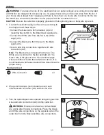
Wiring   . . . . . . . . . . . . . . . . . . . . . . . . . . . . . . . . . . . . . . . . . . . . . . . . . . . . . . . . . . . . . . . . . . . . . . . . . 11

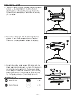
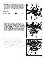
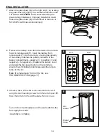
Final Installation. . . . . . . . . . . . . . . . . . . . . . . . . . . . . . . . . . . . . . . . . . . . . . . . . . . . . . . . . . . . . . . . . . 12

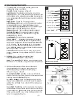
Operating Instructions  . . . . . . . . . . . . . . . . . . . . . . . . . . . . . . . . . . . . . . . . . . . . . . . . . . . . . . . . . . . . . 15

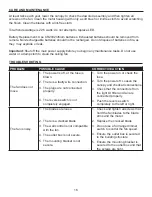
Care and Maintenance   . . . . . . . . . . . . . . . . . . . . . . . . . . . . . . . . . . . . . . . . . . . . . . . . . . . . . . . . . . . . 16

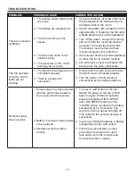
Troubleshooting . . . . . . . . . . . . . . . . . . . . . . . . . . . . . . . . . . . . . . . . . . . . . . . . . . . . . . . . . . . . . . . . . . 16

Limited Lifetime Warranty  . . . . . . . . . . . . . . . . . . . . . . . . . . . . . . . . . . . . . . . . . . . . . . . . . . . . . . . . . . 18

Replacement Parts List  . . . . . . . . . . . . . . . . . . . . . . . . . . . . . . . . . . . . . . . . . . . . . . . . . . . . . . . . . . . . 19

Summary of Contents for CUMBERLAND 42476

Page 1: ..._________________________ ITEM 3856484 1059425 CUMBERLAND CEILING FAN MODEL 42476 42479 SM21527 Questions problems missing parts Before returning to your retailer call our customer service department...

Page 2: ...4 Safety Information 5 Preparation 6 Initial Installation 7 Standard or Angle Mounting Instructions 9 Wiring 11 Final Installation 12 Operating Instructions 15 Care and Maintenance 16 Troubleshooting...

Page 3: ...Yoke Cover 1 H Motor Assembly 1 I Set Screw preassembled to the Motor Assembly H 2 J Mounting Bracket Screw preassembled to the Mounting Bracket D 4 K Fitter Plate preassembled to the Motor Assembly...

Page 4: ...4 HARDWARE CONTENTS Wire Connector Qty 3 1 extra Blade Screw Qty 18 1 extra Blade Washer Qty 18 1 extra Motor Screw Qty 12 1 extra XX shown actual size AA BB CC...

Page 5: ...se a loud humming noise from the fan To reduce the risk of fire or electric shock do NOT use this fan with any solid state speed control device WARNING To reduce the risk of fire electric shock or per...

Page 6: ...interference will not occur in a particular installation If this equipment does cause harmful interference to radio or television reception which can be determined by turning the equipment off and on...

Page 7: ...ncluded Angle Mounting is best suited for angled or vaulted ceilings A longer downrod is sometimes necessary to ensure proper blade clearance Important If using the angle mount check to ensure the cei...

Page 8: ...e direction Detach mounting bracket D from canopy E 5 Attach mounting bracket D to outlet box not included using screws and washers provided with the outlet box CAUTION It is very important to use the...

Page 9: ...rt the downrod A or a longer downrod not included if required through the canopy E and yoke cover G Feed the wires from the fan through the downrod A 3 Slide the downrod A into the yoke align the hole...

Page 10: ...in of insulation from the end of the white wire Twist the stripped ends of each strand of wire within the insulation with pliers not included Repeat the step for the black wire Note If you did not cu...

Page 11: ...wire Connect the Black wire from the fan to the Black supply wire Secure all wiring connections together with wire connectors AA Note The Black wire is hot power for the fan The White wire is common...

Page 12: ...et screws J previously removed Step 4 page 8 Tighten all mounting bracket screws J securely 3 Partially insert the blade screws BB along with the blade washers CC through the blade T blade arm S and i...

Page 13: ...ith the loosened fitter plate screws L Place the light pan M over the three screws and turn the light pan M clockwise Then tighten the three fitter plate screws L Re install the fitter plate screw L t...

Page 14: ...suring the polarity of the battery matches the polarity indicated in the battery compartment positive to positive and negative to negative Replace the battery cover and press the fan power button on t...

Page 15: ...on to activate Light will blink twice to confirm Home Sheild is active Press any button to cancel LED indicator should illuminate when any remote button is pressed If not replace the DC3V CR2032 batte...

Page 16: ...The fan does not move 1 The power is off or the fuse is blown 2 There is a faulty wire connection 3 The plugs are not connected properly 4 The reverse switch is not completely engaged 1 Turn the powe...

Page 17: ...until secure The fan operates correctly but the lights are not working 1 The light kit wire plugs are not connected properly 2 There is a faulty wire connection 1 Ensure that the 6 pin connectors from...

Page 18: ...arying climate conditions this warranty does not cover any changes in brass finish including rusting pitting corroding tarnishing or peeling Brass finishes of this type give their longest useful life...

Page 19: ...00006400 4L000013340 D Mounting Bracket 4L000007490 4L000008860 E Canopy 4L000007510 4L000014940 F Canopy Cover 4L000000830 4L000010400 G Yoke Cover 4A000005540 4A000009350 O Light Kit 4L000015390 4L0...

Reviews: