background image

32

Lowes.com/harborbreeze

CABLEADO

  Conector de cables E3                                  x 4

 2. 

2

Aditamentos utilizados

CC

CC

CC

CC

1b. 

VENTILADOR CONTROLADO POR CADENA DE 

TIRO Y LUZ CONTROLADA POR INTERRUPTOR DE 
PARED:

 Si desea controlar la luz del ventilador con un 

interruptor de pared separado, conecte el conductor 
NEGRO del ventilador con el conductor NEGRO del 
techo. Conecte el conductor AZUL del ventilador al 
conductor NEGRO


(o


ROJO) del interruptor de pared 

independiente para la luz. Conecte el conductor 
BLANCO del ventilador al conductor BLANCO del techo. 
Conecte todos los conductores de PUESTA A TIERRA 
(VERDES) juntos desde el ventilador (en la varilla (A) y 
abrazadera de montaje (C)) con el conductor DESNUDO 
o VERDE del techo. 

1c. 

VENTILADOR Y LUZ CONTROLADOS POR DOS 

INTERRUPTORES DE PARED:

 Si desea controlar el 

ventilador y la luz con interruptores de pared separados, 
conecte el conductor NEGRO del ventilador al conductor 
NEGRO del interruptor de pared independiente para el 
ventilador. Conecte el conductor AZUL del ventilador al 
conductor NEGRO


(o


ROJO) del otro interruptor de 

pared independiente para la luz. Conecte el conductor 
BLANCO del ventilador al conductor BLANCO del techo. 
Conecte todos los conductores de PUESTA A TIERRA 
(VERDES) juntos desde el ventilador (en la varilla (A) y 
abrazadera de montaje (C)) con el conductor DESNUDO 
o VERDE del techo.

NOTA:

 El conductor NEGRO es el que proporciona 

alimentación al ventilador. El conductor AZUL es el que 
proporciona alimentación al kit de iluminación. El 
conductor BLANCO es el conductor común para el 
ventilador y el kit de iluminación. El conductor DESNUDO 
o VERDE es la puesta a tierra.

Cubra con cinta aislante (no se incluye) cada conector 
de cables (CC) individual hacia abajo del cable.


ADVERTENCIA:

 Asegúrese de que no haya 

conductores desnudos ni filamentos de conductores 
visibles después de hacer la conexión. Coloque las 
conexiones VERDES y BLANCAS en el lado opuesto de 
las conexiones NEGRAS y AZULES de la caja (si 
corresponde).

Gire los conductores empalmados o cubiertos con cinta 
hacia arriba y empuje suavemente los conductores y los 
conectores de cables (CC) hacia dentro de la caja de 
salida.

NEGRO

(INTERRUPTOR

DE PARED

PARA LA LUZ)

NEGRO

(INTERRUPTOR DE PARED)

BLANCO (NEUTRO)

PUESTA A TIERRA/VERDE 

(DESNUDO)

VENTILADOR CONTROLADO POR CADENA DE TIRO Y LUZ 
CONTROLADA POR INTERRUPTOR DE PARED

NEGRO

AZUL

1c

BLANCO

VENTILADOR Y LUZ CONTROLADOS POR DOS 
INTERRUPTORES DE PARED

NEGRO

NEGRO
(INTERRUPTOR
DE PARED)

NEGRO (ALIMENTACIÓN)

BLANCO (NEUTRO)

PUESTA A TIERRA/VERDE 

(DESNUDO)

NEGRO

AZUL

1b

BLANCO

NEGRO

ALIMENTACIÓN 
DE 120 V DESDE 
EL TECHO

ALIMENTACIÓN 
DE 120 V DESDE 
EL TECHO

VERDE

VERDE

VERDE

VERDE

Summary of Contents for E-BDB52BNK5BC4N

Page 1: ...1 MODEL E BDB52LABZ5BC4N E BDB52BNK5BC4N E BDB52LW5BC4N E BDB52MBK5BC4N ATTACH YOUR RECEIPT HERE Serial Number Purchase Date Questions problems missing parts Before returning to your retailer call our...

Page 2: ...urned to the factory for repairs it must be shipped in its original packaging to ensure proper protection against damage that might exceed the initial cause for return Make sure all electrical connect...

Page 3: ...g fan lead wires consult an electrician for the proper size wire connectors to use To reduce the risk of fire or electrical shock do not use the fan with any solid state speed control device or contro...

Page 4: ...ovided with this fan for proper installation and safety PACKAGE CONTENTS 4 Lowes com harborbreeze A Downrod 1 B Canopy 1 C Mounting Bracket 1 preassembled D Motor Housing 1 E Glass Shade 4 F Blade 5 G...

Page 5: ...on foam to avoid damage to finish Compare parts with package contents list and hardware contents list If any part is missing or damaged do not attempt to install operate or assemble the product Estima...

Page 6: ...e sure the ceiling angle is not steeper than 19 Helpful Hint Downrod style mounting is best suited for ceilings 8 ft or higher For taller ceilings you may want to use a longer downrod not included Ang...

Page 7: ...TIAL INSTALLATION 7 Lowes com harborbreeze 5 Remove motor screws I and lock washers K from underside of motor housing D If there are plastic motor blocks installed with the motor screws I and lock was...

Page 8: ...harborbreeze 1 Slip downrod A into yoke align holes and re install pin M and clip N Tighten set screws in yoke and then tighten nuts on the set screws Set Screw and Nut B A 2 Remove pin M and clip N f...

Page 9: ...teps 4 and 5 are not necessary and you may proceed to Step 6 instead 4 Ball 5 Install ball end of downrod A into opening of mounting bracket C Align slot in ball with tab in mounting bracket C DANGER...

Page 10: ...g is more suitable for ceilings lower than 8 ft high The downrod A and canopy cover are not used in this type of installation 1 Canopy Cover Remove every other screw and lock washer from top of motor...

Page 11: ...FAN MOUNTING 4 11 Lowes com harborbreeze WIRING Choose wiring diagram Fig 1a Fig 1b or Fig 1c that fits your situation and make appropriate wiring connections as follows NOTE Use one of the wire conn...

Page 12: ...wire from fan to WHITE wire from ceiling Connect all GROUND GREEN wires together from fan on downrod A and mounting bracket C to BARE GREEN wire from ceiling 1c FAN AND LIGHT CONTROLLED BY TWO WALL SW...

Page 13: ...oud humming noise from fan To reduce the risk of fire or electrical shock do NOT use a full range dimmer switch to control fan speed 3 1 FINAL INSTALLATION 1 Dimmer Switch Speed Switch For illustrativ...

Page 14: ...n motor screws I securely Repeat with remaining blade arms G making sure to completely secure each blade arm G before proceeding with the next If you do NOT wish to use the light kit skip to Step 9 If...

Page 15: ...kit fitter R with reverse switch on switch housing for the proper fit Then re insert the light kit fitter screws Q previously removed Step 4 page 14 and use a Phillips screwdriver not included to secu...

Page 16: ...ight pull chains 9 OPERATING INSTRUCTIONS 2 If applicable the pull chain located in the middle is used to turn the lights ON or OFF The pull chain located on the switch housing has four positions to c...

Page 17: ...e A ceiling fan will allow you to raise your thermostat setting in summer and lower your thermostat setting in winter without feeling a difference in your comfort NOTE Wait for fan to stop before movi...

Page 18: ...or check fuse 3 Turn power off Loosen canopy and check all connections Noisy operation 1 Blades are loose 2 Cracked blade 3 Full range dimmer switch 4 Fan is new 1 Tighten all blade screws 2 Replace...

Page 19: ...warranty call our customer service department at 1 800 643 0067 for return authorization and shipping instructions so that we may repair or replace the ceiling fan Any fan or parts returned improperly...

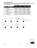
Page 20: ...DESCRIPTION 0152426 0156738 0158620 0204925 PART PART PART PART A Downrod B Canopy C Mounting Bracket F Blade G Blade Arm O Switch Housing Cap R Light Kit Fitter S Socket Ring 0152426 A 0152426 B 015...

Page 21: ...ABZ5BC4N E BDB52BNK5BC4N E BDB52LW5BC4N E BDB52MBK5BC4N ADJUNTE SU RECIBO AQU N mero de serie Fecha de compra Preguntas problemas piezas faltantes Antes de volver a la tienda llame a nuestro Departame...

Page 22: ...ual de cableado H galo usted mismo Aseg rese de que en el sitio de instalaci n que elija se pueda establecer una distancia m nima de 2 13 m entre las aspas y el piso Aseg rese tambi n de que los extre...

Page 23: ...consulte a un electricista cu l es el tama o adecuado de los conectores de cables que debe utilizar Para reducir el riesgo de incendios o descargas el ctricas no use el ventilador con dispositivos de...

Page 24: ...preensamblado 1 N Sujetador preensamblado 1 O Tapa de la carcasa del 1 interruptor preensamblada P Tornillo de la carcasa del 3 interruptor preensamblado Q Tornillo del soporte del kit 3 de iluminaci...

Page 25: ...os Herramientas necesarias para el ensamblaje no se incluyen Cinta aislante destornillador Phillips pinzas gafas de seguridad escalera de tijera y pinzas pelacables Herramientas tiles no se incluyen L...

Page 26: ...en ngulo verifique que el ngulo del techo no tenga una inclinaci n superior a los 19 Consejo til El montaje de varilla es mejor para los techos de 2 44 m o m s de alto Para techos m s altos le recomen...

Page 27: ...andelas planas que incluye con la caja de salida NOTA Es muy importante que use los aditamentos adecuados para instalar la abrazadera de montaje C ya que sta soportar el ventilador IMPORTANTE Si reali...

Page 28: ...M y el sujetador N de la varilla A Afloje parcialmente los tornillos de fijaci n y las tuercas preensambladas en la horquilla en la parte superior del bastidor del motor D 1 Deslice la varilla A en l...

Page 29: ...6 en su lugar 4 Bola Si decidi cortar los cables conductores en el Paso 4 pele 1 27 cm del aislamiento en el extremo del conductor blanco Tuerza los extremos pelados de cada filamento de conductor de...

Page 30: ...techos de menos de 2 44 m de alto La varilla A y la cubierta de la base no se utilizan en este tipo de instalaci n 1 Cubierta de la base 2 3 B 1 D B 3 Jale los cables a trav s del orificio en el cent...

Page 31: ...electricista profesional determine el cableado adecuado Escoja el diagrama de cableado Fig 1a Fig 1b o Fig 1c que se ajuste a su situaci n y realice las conexiones del cableado adecuadas como se indi...

Page 32: ...RDES juntos desde el ventilador en la varilla A y abrazadera de montaje C con el conductor DESNUDO o VERDE del techo NOTA El conductor NEGRO es el que proporciona alimentaci n al ventilador El conduct...

Page 33: ...o con tres arandelas para aspa de fibra BB para conectar un brazo del aspa G a un aspa F Luego apriete cada uno de los tornillos para aspa AA comenzando por el que est en el centro Repita el procedimi...

Page 34: ...onecte el conductor molex AZUL o NEGRO de la carcasa del interruptor al conductor molex NEGRO del soporte del kit de iluminaci n R Aseg rese de que las conexiones molex sean seguras 5 4a Localice los...

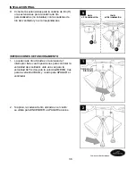
Page 35: ...34 y use un destornillador Phillips no incluido para asegurar todos los tornillos del soporte del kit de iluminaci n Q Carcasa del interruptor 6 Retire los anillos del portal mpara S de los portal mpa...

Page 36: ...NCIONAMIENTO La cadena de tiro ubicada en la carcasa del interruptor tiene cuatro posiciones para controlar la velocidad del ventilador Jale una vez para la velocidad ALTA dos para la velocidad MEDIA...

Page 37: ...mas m s c lidos la configuraci n del interruptor de reversa en la posici n DOWN ABAJO crear un flujo de aire descendente que generar un efecto de viento refrescante 3B En climas m s fr os la configura...

Page 38: ...ado 3 La conexi n de los cables es incorrecta 1 Mueva firmemente el interruptor hacia arriba o hacia abajo 2 Conecte la alimentaci n o revise el fusible 3 Desconecte la alimentaci n Afloje la base y r...

Page 39: ...nterruptor de pared del ventilador est apagado 4 Los conductores de la carcasa del interruptor no est n conectados correctamente 5 El kit de iluminaci n cuenta con l mparas de m s de los 190 vatios pe...

Page 40: ...l acabado de lat n oxidaci n picaduras deslustre corrosi n o descascarado Los ventiladores con acabado de lat n mantienen su belleza cuando se les protege de las condiciones clim ticas cambiantes La g...

Page 41: ...PIEZA DESCRIPCI N 0152426 0156738 0158620 0204925 PIEZA PIEZA PIEZA PIEZA A Varilla B Base C Abrazadera de montaje F Aspa G Brazo de aspa O Tapa de la carcasa del interrupton R Soporte del kit de ilu...

Reviews: