background image

17

Lowes.com/harborbreeze


CAUTION:

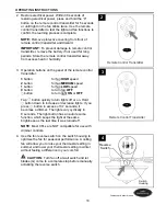
 The remote control transmitter can be programmed to multiple receivers or fans. 

If this is not desired, turn wall switch off to any other programmable receiver or fan.

OPERATING INSTRUCTIONS

FCC Compliance Notice for Remote Control

Modifications not approved by the party responsible for compliance could void the user's authority 
to operate the equipment.

*NOTE: This equipment has been tested and found to comply with the limits for a Class B digital 
device, pursuant to Part 15 of the FCC Rules. These limits are designed to provide reasonable 
protection against harmful interference in a residential installation. This equipment generates, 
uses and can radiate radio frequency energy and, if not installed and used in accordance with 
the instructions, may cause harmful interference to radio communications. However, there is no 
guarantee that interference will not occur in a particular installation. If this equipment does cause 
harmful interference to radio or television reception, which can be determined by turning the 
equipment off and on, the user is encouraged to try to correct the interference by one or more of 
the following measures:

        *      Reorient or relocate the receiving antenna.
        *      Increase the separation between the equipment and receiver.
        *      Connect the equipment into an outlet on a circuit different from that to which the
 

     receiver is connected.

Consult the dealer or an experienced radio/TV technician for help.

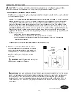
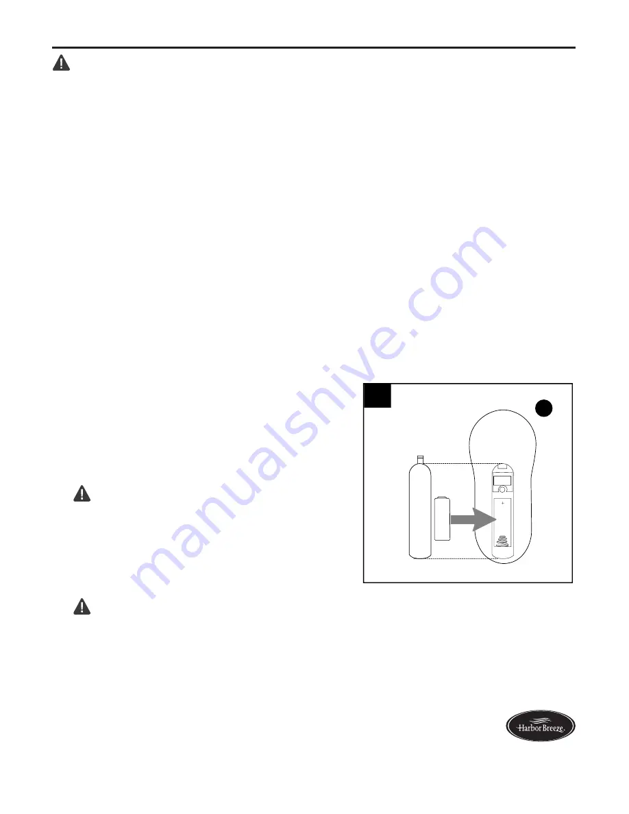
Remove battery cover from back of remote 
control transmitter in remote pack (U). Install 
battery from remote pack (U) with positive (+) 
end toward top of remote control transmitter. 

Replace battery cover on remote control 
transmitter.


WARNING

Choking Hazard

 - Small parts.

Keep battery away from children.

 1. 

(back

side)

1

Battery

Cover

U


CAUTION:

 “DO NOT DISPOSE OF BATTERIES IN FIRE, BATTERIES MAY EXPLODE OR 

LEAK.” - When disposing of household alkaline batteries, it is best to check with your local and 
state recycling or household hazardous waste coordinators concerning the specifics of the 
program in your area. You may also locate a recycling center by calling 1-800-8-BATTERY or 
1-877-2-RECYCLE or visit www.epa.gov/epawaste/index.htm or www.earth911.org for more 
information.

Remote

Control

Transmitter

Battery

Summary of Contents for E-CAF56OSB5CRC

Page 1: ...MODEL E CAF56OSB5CRC Questions problems missing parts Before returning to your retailer call our customer service department at 1 800 643 0067 8 a m 6 p m EST Monday Thursday 8 a m 5 p m EST Friday A...

Page 2: ...s are secure to prevent the fan from falling The net weight of this fan including the light kit is 18 73 lbs Safety Information 2 Package Contents 4 Hardware Contents 5 Preparation 5 Initial Installat...

Page 3: ...one 12 gauge house wire and two lead wires from the fan If your house wire is larger than 12 gauge or there is more than one house wire to connect to the corresponding fan lead wires consult an electr...

Page 4: ...ousing Cap 1 preassembled DESCRIPTION PART QUANTITY N Switch Housing Cap Screw 3 preassembled O Finial preassembled 1 P Glass Shade 1 Q Rubber Washer 1 preassembled R Balancing Kit 1 S Motor Screw 10...

Page 5: ...ardware contents list If any part is missing or damaged do not attempt to install operate or assemble the product Estimated Assembly Time 120 minutes Tools Required for Assembly not included Electrica...

Page 6: ...d to use A Downrod mount standard or angled ceiling B Closemount standard ceiling only IMPORTANT If using the angle mount check to make sure the ceiling angle is not steeper than 19 Helpful Hint Downr...

Page 7: ...support the fan IMPORTANT If using the angle mount make sure open end of mounting bracket C is installed facing the higher point of the ceiling and ensure the ceiling angle is not steeper than 19 4b...

Page 8: ...1 1 X D W A Yoke Set Screw and Nut Sideview 2 Insert downrod A through canopy B and yoke cover E Then thread wires from motor housing D up through downrod A 2 B A 3 Slip downrod A into yoke align hole...

Page 9: ...ire cutters not included NOTE If you do not cut back the lead wires Steps 4 and 5 are not necessary and you may proceed to Step 6 instead 4 Hanging Ball 4 8 in 6 If you decided to cut back the lead wi...

Page 10: ...tapping on the canopy cover from the inside of the canopy B NOTE The downrod A yoke cover E and canopy cover are not used in this type of installation 1 1 3 Pull wires up through hole in the middle o...

Page 11: ...ctrician CAUTION Be sure outlet box is properly grounded and that a ground green or bare wire is present WARNING The wires from the outlet box must be connected to a corresponding color of the fan s w...

Page 12: ...EEN wires from fan on downrod A if applicable and mounting bracket C to BARE GREEN supply wire from ceiling Connect BLACK wire labeled AC IN L from remote control receiver H to BLACK supply wire from...

Page 13: ...ing with the one in the middle Repeat for remaining blades G and blade arms J Hardware Used Blade Screw x 15 BB Blade Washer x 15 CC CC BB G J Downrod Closemount B B A D D Z Y FINAL INSTALLATION 3 Gen...

Page 14: ...ousing cap M with holes in switch housing Note Make sure to align notch on top edge of the switch housing cap M with the reverse switch on switch housing for the correct fit Re insert the switch housi...

Page 15: ...until threaded rod comes through hole Secure glass shade P with hex nut K CAUTION Do NOT overtighten hex nut K as glass may crack or break Then align hole in center of finial plate I with threaded ro...

Page 16: ...e Used Cap x 1 AA Place cap AA firmly in hole in middle of switch housing cap M Align holes in switch housing cap M with holes in switch housing then attach switch housing cap M with previously remove...

Page 17: ...be determined by turning the equipment off and on the user is encouraged to try to correct the interference by one or more of the following measures Reorient or relocate the receiving antenna Increas...

Page 18: ...button for fan MEDIUM speed 1 button for fan LOW speed 0 button to turn fan OFF button to turn light ON or OFF Tap button quickly to turn lights off or on Hold button down to increase or decrease lig...

Page 19: ...the middle position fan will not operate 4a 4b 4c CARE AND MAINTENANCE At least twice each year lower canopy B to check downrod A assembly and then tighten all screws on fan Clean motor housing D with...

Page 20: ...eds 5 Verify mounting bracket is secure according to instructions on page 7 TROUBLESHOOTING Excessive wobbling 1 Blades are loose 2 Blade arms incorrectly attached 3 Unbalanced blades 4 Fan not secure...

Page 21: ...imatic conditions this warranty does not cover changes in brass finish rusting pitting tarnishing corroding or peeling Brass finish fans maintain their beauty when protected from varying weather condi...

Page 22: ...5 p m EST Friday Printed in China Harbor Breeze is a registered trademark of LF LLC All Rights Reserved A B C G I A Downrod B Canopy C Mounting Bracket F Light Kit Fitter G Blade J Blade Arm M Switch...

Reviews: