background image

13

FINAL INSTALLATION

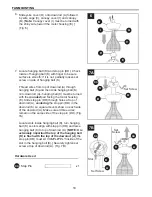
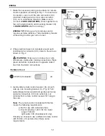
 1.  Locate two canopy mounting screws (N) on 

underside of mounting bracket (C) and remove 
canopy mounting screw (N) closest to the open end 
of the mounting bracket (C). Partially loosen the 
other canopy mounting screw (N). Lift canopy (B) to 
mounting bracket (C). Place rounded part of slotted 
hole in canopy (B) over loosened canopy mounting 
screw (N) in mounting bracket (C) and push up. 
Twist canopy (B) to lock. Re-insert canopy mounting 
screw (N) that was removed, and then tighten both 
canopy mounting screws (N). Slide canopy cover (I) 
up to canopy (B), aligning rounded part of slotted 
holes in canopy cover (I) with screwheads in bottom 
of canopy (B). Turn canopy cover (I) to the right 
(clockwise) until it stops. (Fig. 1)

B

N

I

1

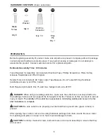
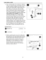
WIRING

1

2

3

Dimmer 

Switch

Speed 

Switch

For illustrative purposes only

--

not 

intended to cover all types of controls

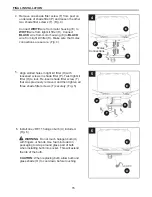
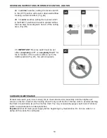
IMPORTANT

: Using a full range dimmer switch (not 

included) to control fan speed will cause a loud 
humming noise from fan. To reduce the risk of fire or 
electrical shock, do NOT use a full range dimmer 
switch to control fan speed. (Fig. 4)

 4. 

4

Summary of Contents for E-ER56ORB3LKLR

Page 1: ...call or contact our customer service department at 1 800 527 1292 8 30 a m 5 00 p m CST Monday Friday ATTACH YOUR RECEIPT HERE Serial Number Purchase Date Espa ol p 23 E192641 Federal regulations requ...

Page 2: ...T Monday Friday Do not discard fan carton or foam inserts Should this fan need to be returned to the factory for repairs it must be shipped in its original packaging to ensure proper protection agains...

Page 3: ...this fan are designed to accept only one 12 gauge house wire and two lead wires from the fan If your house wire is larger than 12 gauge or there is more than one house wire to connect to the two fan...

Page 4: ...me by deciding which options are best suited for your needs before beginning the steps outlined in this manual Your fan can be installed on a normal or angled ceiling Two points to remember before you...

Page 5: ...e Fitter 1 Q Remote Control 1 Transmitter R 12 volt Battery 1 S Remote Control Receiver 1 T Shade Fitter Screw 3 U Halogen Bulb 1 V Wire Cage 1 PART DESCRIPTION QUANTITY A Downrod 1 B Canopy 1 C Mount...

Page 6: ...Handbook available at Lowe s and Wire Cutters Bulb Required included One 75 watt max halogen bulb size JD E11 DANGER When using an existing outlet box make sure the outlet box is securely attached to...

Page 7: ...s injury or death 1 Determine mounting method to use Fig 2 A Normal mount B Angle mount Important If using the angle mount check to make sure the ceiling angle is not steeper than 19 2 Check to make s...

Page 8: ...from motor housing yoke at top of motor housing E and partially loosen set screws Fig 1 Helpful Hint Downrod style mounting is best suited for ceilings 8 ft 2 44 m high or higher For taller ceilings...

Page 9: ...on the length of downrod A you use you may need to cut the lead wires back to simplify the wiring If you decide to cut back the lead wires it is suggested that you do so in the following manner Take...

Page 10: ...ke sure all three wires remain on the same side of the stop pin DD Fig 7A Locate slots inside hanging ball K turn hanging ball K so slots align with stop pin DD and raise hanging ball K to top of down...

Page 11: ...instructions for remote control WARNING To reduce the risk of fire electrical shock or personal injury wire connectors provided with this fan are designed to accept only one 12 gauge house wire and t...

Page 12: ...wn in Fig 2 WARNING Make sure no bare wire or wire strands are visible after making connections Place green and white connections on opposite side of box from the black connections E3 Wire Connector x...

Page 13: ...nting screw N that was removed and then tighten both canopy mounting screws N Slide canopy cover I up to canopy B aligning rounded part of slotted holes in canopy cover I with screwheads in bottom of...

Page 14: ...F facing up After inserting one blade screw AA along with one lock washer BB through center hole in blade plate F and blade G align that blade screw AA with center hole in one set of three holes on u...

Page 15: ...ne shade fitter screw T from post on underside of shade fitter P and loosen the other two shade fitter screws T Fig 4 Connect WHITE wire from motor housing E to WHITE wire from light kit fitter H Conn...

Page 16: ...attery R provided and then replace battery cover on remote control transmitter Q Fig 1 1 back CAUTION The remote control transmitter Q can be programmed to multiple receivers or fans If this is not de...

Page 17: ...d for long periods Store the remote control transmitter Q away from excess heat or humidity 2 Q front CHANGING REVERSE SWITCH SETTING 1 Locate reverse switch on top half of motor housing E If reverse...

Page 18: ...function that keeps the light at the same brightness as the last time it was turned off IMPORTANT Turn fan off at wall switch and let blades G come to a complete stop before manually activating the r...

Page 19: ...reverse switch in the RIGHT position will result in upward airflow that can help move stagnant hot air off the ceiling area Fig 2B At least twice each year lower canopy B to check downrod A assembly a...

Page 20: ...ally when running the fan at Medium and High speeds Excessive wobbling 1 Blades G are loose 2 Blade plates F incorrectly attached 3 Unbalanced blades G 4 Fan not securely mounted 5 Fan too close to va...

Page 21: ...rom varying weather conditions Any glass provided with this fan is not covered by the warranty Any replacement of defective parts for the ceiling fan must be reported within the first year from the da...

Page 22: ...of the fan available which can be found on page 1 A D B F C G J T CC PART DESCRIPTION A Downrod B Canopy C Mounting Bracket D Yoke Cover F Blade Plate G Blade H Light Kit Fitter I Canopy Cover J Fitte...

Page 23: ...l de lunes a viernes ADJUNTE SU RECIBO AQUI N mero de serie Fecha de compra Harbor Breeze es marca registrada de LF LLC Reservados todos los derechos E192641 Los reglamentos federales requieren que lo...

Page 24: ...st ndar No deseche la caja del ventilador ni los accesorios de espuma En caso de que deba devolverse este ventilador a la f brica para realizarle reparaciones debe ser enviado en su empaque original p...

Page 25: ...dise ados para soportar s lo un cable interior de calibre 12 y dos cables conductores del ventilador Si el cable interior es de un calibre superior a 12 o hay m s de un cable interior para conectar lo...

Page 26: ...es se adaptan mejor a sus necesidades antes de comenzar a realizar los pasos detallados en este manual Puede instalar el ventilador en techos normales o en ngulo Dos puntos que debe recordar antes de...

Page 27: ...Receptor del control 1 remoto T Tornillo del conectador 3 para la pantalla U Bombilla hal gena 1 V Caja de metal 1 A Varilla 1 B Cubierta 1 C Soporte de montaje 1 D Cubierta de la horquilla 1 E Carca...

Page 28: ...Bombilla requerida se incluye 1 bombilla hal gena de 75 vatios como m ximo tama o JD E11 PELIGRO Si utiliza una caja de salida existente aseg rese de que est bien sujeta a la estructura del edificio...

Page 29: ...talaci n pueden producirse lesiones graves o la muerte 1 2 Verifique que las aspas G est n alejadas al menos 76 20 cm de cualquier obstrucci n Verifique el largo de la varilla A para asegurarse de que...

Page 30: ...la parte superior de la carcasa del motor E y suelte parcialmente los tornillos de fijaci n Fig 1 Sugerencia til El montaje de varilla es mejor para los techos de 2 44 m o m s de alto Para techos m s...

Page 31: ...y el ventilador Dependiendo del largo de la varilla A que utilice es posible que necesite cortar los cables conductores para simplificar el cableado Si decide cortar los cables conductores se sugiere...

Page 32: ...n en el mismo lado del perno de tope DD Fig 7A Localice las ranuras dentro de la bola para colgar K gire la bola para colgar K para que las ranuras se alineen con el perno de tope DD y suba la bola pa...

Page 33: ...nductores del ventilador preg ntele a un electricista cu l es el tama o adecuado de los conectores de cables que debe utilizar PRECAUCI N Aseg rese de que la caja de salida tenga la debida puesta a ti...

Page 34: ...entiladores de estado s lido b Clasificaci n el ctrica 120V 60 Hz amperaje MAX del motor 1 5 vatios de luz 300 s lo incandescente Si usted desea usar otro control remoto con este ventilador ste tambi...

Page 35: ...base N Deslice la cubierta de la base I hacia arriba hasta la base B alineando la parte redondeada de los orificios ranurados en la cubierta de la base I con las cabezas de los tornillos en la parte i...

Page 36: ...de seguridad BB en el orificio central de la placa del aspa F y el aspa G alinee dicho tornillo para aspa AA con el orificio central en uno de los juegos de tres orificios en la parte inferior de la c...

Page 37: ...dos tornillos del soporte de la pantalla T Fig 4 Conecte el conductor BLANCO de la carcasa del motor E al conductor BLANCO del soporte del kit de iluminaci n H Conecte el conductor NEGRO de la carcasa...

Page 38: ...el interruptor reductor de luz est etiquetado con una D y una X El interruptor reductor de luz viene ya puesto en posici n ENCENDIDO D Si no desea tener funcionalidad de interruptor de luz usted puede...

Page 39: ...to Q lejos del calor excesivo o la humedad 2 Q lado principal CAMBIO DE CONFIGURACI N DEL INTERRUPTOR DE REVERSA 1 Ubique el interruptor de reversa en la mitad de la parte de arriba en la carcasa del...

Page 40: ...na funci n que permite que al encender la luz sta se enciende autom tica mente en la brillantez en la cual la hab a dejado antes de apagarla IMPORTANTE Apague el ventilador en el interruptor de la par...

Page 41: ...onfiguraci n del interruptor de reversa en la posici n a la DERECHA crear un flujo de aire ascendente que puede ayudar a mover el aire caliente estancado fuera del rea del techo Fig 3B Al menos dos ve...

Page 42: ...das correctamente 3 Las aspas G no est n equilibradas 4 El ventilador no est bien montado 5 El ventilador est demasiado cerca del techo de b veda 6 El los tornillo s de fijaci n en la horquilla de la...

Page 43: ...Vuelva a instalar la bombilla 2 Revise los conductores de la base B y si es necesario vuelva a conectarlos de acuerdo con las instrucciones de la p gina 34 3 Aseg rese de que el interruptor de pared d...

Page 44: ...pos de condiciones clim ticas esta garant a no cubre ning n cambio en el acabado bronce ni por la oxidaci n marcas la decoloraci n la corrosi n ni el descascarillado del material Se conserva la bellez...

Page 45: ...bierta O Pantalla de vidrio P Soporte de la pantalla T Tornillo del soporte de la pantalla AA Tornillo para aspa BB Arandela de seguridad CC Conector para cable E3 DD Perno de tope Para piezas de repu...

Reviews: