background image

SAFETY INFORMATION  

Lowes.com/harborbreeze

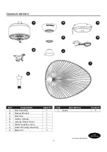
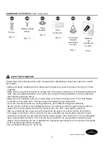
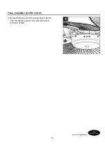
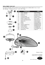
Before beginning assembly of product, make sure all parts are present. Compare parts with
package contents list and hardware contents list. If any part is missing or damaged, do not 
attempt to assemble the product. 

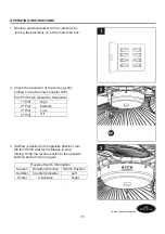
Estimated Assembly Time: 60 minutes

Tools Required for Assembly (not included): Phillips screwdriver, 1/4 in. flathead screwdriver, 
wire stripper and step ladder.
Helpful Tools (not included): AC tester light, do-it-yourself wiring handbook and wire cutters.
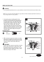
PREPARATION

WARNING

‡'RQRWLQVWDOORUXVHIDQLIDQ\SDUWLVGDPDJHGRUPLVVLQJ
‡7RUHGXFHWKHULVNRIILUHHOHFWULFDOVKRFNRUSHUVRQDOLQMXU\ZLUHFRQQHFWRUVSURYLGHGZLWKWKLV

    fan are designed to accept only one 12-gauge house wire and two lead wires from the fan.  If 
    your house wire is larger than 12-gauge or there is more than one house wire to connect to the 
    two fan lead wires, consult an electrician for the proper size wire connectors to use. Before 
    cutting, drilling or hammering, verify their location. If needed, contact your electrician, plumber
    or service person.

‡

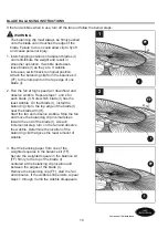
To reduce the risk of fire, electric shock, or personal injury, do not bend the blade arms when

    installing them, balancing the blades, or cleaning the fan. Do not insert foreign objects between 
    the rotating fan blades. Mount to outlet box marked “ACCEPTABLE FOR FAN SUPPORT” and 
    use mounting screws provided with the outlet box. Most outlet boxes commonly used for the 
    support of lighting fixtures are not acceptable for fan support and may need to be replaced. 
    Consult a qualified electrician if in doubt.

‡

This fan is to be used in dry or damp locations.

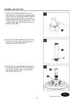
‡5HDGDOOLQVWUXFWLRQVDQGVDIHW\LQIRUPDWLRQEHIRUHLQVWDOOLQJWKHQHZIDQ5HYLHZDFFRPSDQ\LQJ

   assembly diagrams. 

CAUTION

5

Summary of Contents for FREEPORT LP8079LAZ

Page 1: ...er Purchase Date Lowes com harborbreeze Questions problems missing parts Before returning to your retailer call our customer service department at 1 800 643 0067 8 a m 6 p m EST Monday Thursday and 8 a m 5 p m EST Friday Harbor Breeze is a registered trademark of LF LLC All Rights Reserved 1 EB13230 ...

Page 2: ... Contents Safety Information Preparation Assembly Instructions Wiring Instructions Final Assembly Instructions Operating Instructions Blade Balancing Instructions Care and Maintenance Troubleshooting Warranty Replacement Parts List 3 4 4 5 6 10 11 15 16 17 17 19 20 2 ...

Page 3: ...bly 1 B Hanger Bracket 1 C Downrod D Ceiling Canopy 1 E Canopy Screw Cover 1 F Motor Coupling Cover 1 G Switch Housing Assembly 1 H Blade Arm 5 PART DESCRIPTION QUANTITY F G H I 1 B C D E A Lowes com harborbreeze I Blade 5 PACKAGE CONTENTS 3 ...

Page 4: ...ly to the building structure The outlet box and its support must be able to support the moving weight of the fan at least 35 lbs Do NOT use a plastic outlet box After you install the fan make sure all connections are secure to prevent the fan from falling For supply connections if the conductor of a fan is identified as a grounded conductor then it should be connected to a grounded conductor power...

Page 5: ... your house wire is larger than 12 gauge or there is more than one house wire to connect to the two fan lead wires consult an electrician for the proper size wire connectors to use Before cutting drilling or hammering verify their location If needed contact your electrician plumber or service person To reduce the risk of fire electric shock or personal injury do not bend the blade arms when instal...

Page 6: ...down the downrod C Remove the preassembled pin from the downrod C then remove the hanger ball Retain the pin and hanger ball for later 2 Remove the preassembled hairpin clip and clevis pin from the bottom of downrod C Retain the pin and clip for later 3 Loosen the two preassembled set screws in the downrod support of the motor assembly A Route the black white and blue wires through the downrod C 6...

Page 7: ...the canopy screw cover E should be toward the ceiling direction C A 4 6 Reinstall the hanger ball on the downrod C by routing the three 54 in wires from the motor assembly A through the hanger ball Position the pin removed in step 1 through the two holes in the downrod C and align the hanger ball so the pin is captured in the groove in the top of the hanger ball Pull the hanger ball up tight again...

Page 8: ...rical shock be sure electricity is turned off at the main fuse box before hanging WARNING The fan must hang with at least 7 ft of clearance from the floor to blades B 8 8 Securely attach the hanger bracket B to the outlet box not included using the outlet box screws and washers supplied with the outlet box WARNING The outlet box must be securely anchored Hanger bracket must seat firmly against out...

Page 9: ...od C on the hanger bracket B Be sure the groove in the ball is lined up with tab on the hanger bracket B WARNING Failure to seat tab in groove could cause damage to electrical wires and possible shock or fire hazard To avoid possible shock do not pinch wires between the hanger ball assembly and the hanger bracket 9 ...

Page 10: ...pply Blue Wire from Fan Black Wire from Fan 1 Connect the green grounding lead from the downrod C and the green grounding lead from the hanger bracket B to the supply grounding conductor this may be a bare wire or wire with green colored insulation Securely connect wires with wire connector DD Securely connect the white fan motor wire to the white supply neutral wire using wire connector DD Secure...

Page 11: ...ll opening of the keyslot Tighten shoulder screw Re install the previously removed shoulder screw to fully assembly ceiling canopy D to hanger bracket B 2 Securely attach and tighten the canopy screw cover E over the shoulder screws in the hanger bracket B utilizing the keyslot twist lock feature WARNING To avoid possible fire or shock make sure the electrical wires are completely inside the canop...

Page 12: ...nd discard the preassembled motor stops from the motor assembly A by removing the screws 3 A I H 4 Position the blades I over the blade arms H with threaded posts showing Make sure the bottom edge of the blades I are fully seated against the blade arms H Install and tighten the washer head screws BB with fiber washers CC to secure the blades I to the blade arms H Hardware Used BB Washer Head Screw...

Page 13: ...et of the motor assembly A Slightly loosen the remaining two screws Assemble the switch housing assembly G to the support bracket of motor assembly A using the two keyslots in the switch housing assembly G Replace the third screw and secure all three screws 8 Securely attach the connector from the motor assembly A to the wire harness socket within the switch housing assembly G G 7 G A 13 WARNING T...

Page 14: ...Lowes com harborbreeze FINAL ASSEMBLY INSTRUCTIONS 9 Reassemble the switch housing assembly G onto the adaptor switch cup with previously removed screws 9 G 14 ...

Page 15: ...e fan chain coupler EE 1st Pull 2nd Pull 3rd Pull 4th Pull High Off Low Medium Fan Pull Chain Operating Sequence 3 If airflow is desired in the opposite direction turn the fan off and wait for the blades to stop turning Slide the reverse switch to the opposite position and turn fan on again Season Summer Winter Rotation Direction Switch Position Clockwise Counterclockwise Left Right Reverse Switch...

Page 16: ... fan and observe If the wobble still persists repeat steps 1 through 3 until the wobble disappears 2 5XQ WKH IDQ DW KLJK VSHHG DLU GRZQÀRZ DQG observe wobble Repeat steps 1 and 2 for each blade I Note which blade I has the least wobble On that blade I install the balancing clip to the top edge of the blade I near the blade arm H Start the fan and observe wobble Stop the fan and move the balancing ...

Page 17: ...ling fan It could damage the motor or the finish and create the possibility of electrical shock 1 Check main and branch circuit fuses or circuit breakers 2 Check line wire connections to fan and switch wire connections in the switch housings WARNING Make sure main power is turned off WARNING Make sure main power is turned off 4 Check to make sure wire connectors in switch housing are not rattling ...

Page 18: ...ion of fan blades can redistribute the weight and result in smoother operation For example exchange blades in positions 1 and 3 or 1 and 4 If this does not improve wobble exchange 2 and 4 or 2 and 5 2 Tighten the set screw in the downrod hanger ball assembly 3 Check to be sure screws that attach the fan blade holders to the motor hub are tight 4 Check to be sure the fan blade holders seat firmly a...

Page 19: ...ons so that we may repair or replace the ceiling fan Any fan or parts returned improperly packaged is the sole responsibility of the purchaser There is no further expressed warranty The manufacturer disclaims any and all implied warranties The duration of any implied warranty which can not be disclaimed is limited to the lifetime limited period as specified in our warranty The manufacturer shall n...

Page 20: ...H B C E F D A G M BB CC AA FF PART DESCRIPTION PART AMA8079LAZ APGAC110RBL ADRACT1 45LAZ P801301LAZ APPAC1101LAZ AP1115LAZ AP807301LAZ AP807202LAZ AP807203DNA HDWBH8072SS HDWBM8072SS HDWBM8072SS HDWWNUTS4 ALP000002LAZ LBALKT Motor Assembly Hanger Bracket Downrod Ceiling Canopy Canopy Screw Cover Motor Coupling Cover Switch Housing Assembly Blade Arm Blade Screw Washer Head Screw Fiber Washers Wire...

Page 21: ...e LF LLC Todos los derechos reservados ADJUNTAR SU RECIBO AQUÍ Número de serie Fecha de compra Preguntas problemas piezas faltantes Antes de volver a la tienda llame a nuestro Departamento de Servicio al Cliente al 1 800 643 0067 de lunes a jueves de 8 a m a 6 p m y los viernes de 8 a m a 5 p m hora estándar del Este 21 VE ...

Page 22: ...n Instrucciones de ensamblaje Instrucciones de cableado Instrucciones de ensamblaje finales Instrucciones de funcionamiento Instrucciones para balancear las aspas Cuidado y mantenimiento Solución de problemas Garantía Lista de piezas de repuesto 23 24 24 25 26 30 31 35 36 37 37 39 40 ÍNDICE 22 ...

Page 23: ...ZA DESCRIPCIÓN CANTIDAD Ensamble del motor Abrazadera para colgar Varilla Escudo del techo Cubierta para los tornillos de la base Cubierta para el acoplador del motor A B C D E F 1 5 5 PIEZA DESCRIPCIÓN CANTIDAD Ensamble de la carcasa del interruptor Brazo del aspa Aspa G H I 23 ...

Page 24: ...ncia mínima de 2 13 m desde las aspas hasta el piso y al menos a 76 20 cm desde los extremos de las aspas hasta cualquier obstáculo Si desea montar el ventilador en una caja de salida del techo use una caja de salida octagonal de METAL Asegure la caja directamente a la estructura del edificio La caja de salida y su soporte deben ser capaces de sostener el peso del ventilador en movimiento como mín...

Page 25: ...E FOR FAN SUPPORT APTA PARA SOPORTE DE VENTILADOR y use los tornillos de montaje que se proporcionan con la caja de salida La mayoría de las cajas de salida que se usan comúnmente para sostener ensambles de iluminación no son aptas para sostener un ventilador y puede ser necesario reemplazarlas Si tiene dudas consulte con un electricista calificado Este ventilador es apto sólo para lugares secos L...

Page 26: ...tire la bola para colgar Guarde el pasador y la bola para colgar para pasos posteriores 2 Retire el sujetador de horquilla del preensamblado y pasador de horquilla de la parte inferior de la varilla C Guarde el pasador y el sujetador para pasos posteriores 3 Afloje los dos tornillos preensamblados de fijación del soporte de la varilla del ensamble del motor A Pase los conductores negro blanco y az...

Page 27: ...imientode dicho paso podría hacer que el ventilador se caiga 5 Pase los cables a través de la cubierta del acoplador del motor F la cubierta del tornillo de la base E y la base para techo D Nota El chavetero de los la cubierta para el tornillo de la base E debe ser hacia la dirección del techo 6 Vuelva a instalar la bola para colgar en la varilla C haciendo pasar los dos conductores de 1 37 m del ...

Page 28: ...rtar la alimentación eléctrica de la caja de fusibles principal antes de colgar el ventilador ADVERTENCIA Debe colgar el ventilador a una distancia mínima de 2 13 m desde las aspas hasta el piso 8 Fije bien la abrazadera para colgar B a la caja de salida no se incluye con los tornillos y las arandelas provistas con la caja de salida ADVERTENCIA La caja de salida debe estar bien asegurada La abraza...

Page 29: ...egúrese de que la ranura de la bola esté alineada con la lengüeta de la abrazadera para colgar B ADVERTENCIA Si no coloca la lengüeta en la ranura podrían dañarse los cables eléctricos y podrían ocurrir incendios o descargas eléctricas Para evitar una posible descarga eléctrica no apriete los cables entre el ensamble de la bola para colgar y la abrazadera para colgar 29 ...

Page 30: ...lla C y el conductor verde con puesta a tierra de la abrazadera para colgar B al conductor de suministro con puesta a tierra posiblemente un conductor desnudo o un cable con aislante verde Conecte los conductores con conectores de cables DD de forma segura Conecte el conductor blanco del motor del ventilador al conductor blanco neutro mediante el conector DD de forma segura Conecte de forma segura...

Page 31: ...lo de reborde Vuelva a instalar el tornillo de reborde que retiró anteriormente para ensamblar por completo la base para techo D a la abrazadera para colgar B ADVERTENCIA Para evitar una posible descarga eléctrica o incendio asegúrese de colocar los cables eléctricos completamente dentro de la carcasa de la base y de no apretarlos entre la carcasa y el techo 2 Coloque y ajuste firmemente la cubier...

Page 32: ...n los postes roscados que se muestran Asegúrese de que el borde inferior del aspa I son completamente asentado brazos del aspa H del aspa Instale y apriete los tornillos con cabeza BB junto con las arandelas de fibra CC para asegurar las aspas I a los brazos del aspa H ADVERTENCIA Para reducir el riesgo de lesiones personales no doble los soportes de las aspas al instalarlos equilibrar las aspas o...

Page 33: ...l motor A al portalámparas con arnés de cableado que se encuentra dentro del ensamble del carcasa del interruptor G G 7 G A INSTRUCCIONES DE ENSAMBLAJE FINALES 7 Retire uno de los tres tornillos de la abrazadera de soporte del ensamble del motor A Afloje ligeramente los dos tornillos restantes Ensamble el ensamble de la carcasa del interruptor G al soporte de montaje del ensamble del motor A media...

Page 34: ... com harborbreeze 9 Vuelva a ensamblar el ensamble de la carcasa del interruptor G en el soporte del interruptor adaptador con los tornillos que retiró previamente 9 G INSTRUCCIONES DE ENSAMBLAJE FINALES 34 ...

Page 35: ...ada 3 ª tirada 4 ª tirada Alta Apagado Baja Media Secuencia de funcionamiento de la cadena del tirador 3 Si desea que el flujo de aire corra en la dirección opuesta apague el ventilador y espere hasta que las aspas dejen de girar Deslice el interruptor de reversa a la posición opuesta y vuelva a encender el ventilador Temporada Verano Invierno Dirección de rotación Posición del interruptor En dire...

Page 36: ... observe el tambaleo Repita los pasos 1 y 2 para cada aspa I Tenga en cuenta qué aspa I tiene el menor tambaleo Instale en dicha aspa I el sujetador de equilibrio en el borde superior del aspa I cerca de su brazo del aspa H Haga funcionar el ventilador y observe si hay tambaleo Detenga el ventilador y mueva el sujetador de equilibrio a tramos pequeños hacia el extremo del aspa I En cada tramo de i...

Page 37: ...n nueva batería El ventilador emite mucho ruido PROBLEMA CAUSA POSIBLE ACCIÓN CORRECTIVA El ventilador no arranca 1 Se fundió un fusible o el interruptor de circuito 2 Las conexiones de la línea de alimentación eléctrica del ventilador 3 Sin batería en el control remoto de mano 1 Las aspas no están sujetas al ventilador 2 Hay tornillos flojos en la carcasa del motor 3 Los tornillos que sujetan los...

Page 38: ...illos que fijan los soportes de las aspas del ventilador al eje del motor estén ajustados 4 Los soportes de las aspas no están asentados correctamente 4 Compruebe que los soportes de las aspas del ventilador estén firmes y uniformemente asentados en la superficiede la carcasa del motor Si los soportes no están bien asentados afloje los tornillos y vuelva a ajustarlos 5 La abrazadera para colgar y ...

Page 39: ...e corrosión o descascaramiento Los ventiladores con acabado de latón mantienen su belleza cuando se les protege de las cambiantes condiciones atmosféricas La garantía no cubre los elementos de vidrio incluidos con este ventilador El reemplazo de piezas defectuosas para el ventilador de techo debe informarse dentro del primer año a partir de la fecha de compra Para conocer el saldo de la garantía l...

Page 40: ...M AMA8079LAZ APGAC110RBL ADRACT1 45LAZ P801301LAZ APPAC1101LAZ AP1115LAZ AP807301LAZ AP807202LAZ AP807203DNA HDWBH8072SS HDWBM8072SS HDWBM8072SS HDWWNUTS4 ALP000002LAZ LBALKT Ensamble del motor Abrazadera para colgar Varilla Escudo del techo Cubierta para los tornillos de la base Cubierta para el acoplador del motor Ensamble de la carcasa del interruptor Brazo del aspa Aspa Tornillo Tornillo con c...

Reviews: