background image

Blade Screw

Qty 12+1 extra

4

HARDWARE CONTENTS 

SAFETY INFORMATION

(not shown actual size)

AA

READ AND SAVE THESE INSTRUCTIONS

Please read and understand this entire manual before attempting to assemble, operate or install the product. 
.   All electrical connections must comply with local codes, ordinances or the National Electric Code (NEC). 

    Contact your municipal building department to inquire about your local codes, permits and/or inspections.
.   Turn off electricity at main fuse box (or circuit breaker box) before beginning installation by removing fuse 

 or by switching off circuit breaker.

.   Do not connect this fixture to an electrical system that does not provide a means for equipment grounding. 

    Never use a fixture in a two-wire system that is not grounded.
.   If you are not sure your lighting system has a grounding means, do not attempt to install this fixture. Contact 

    a qualified, licensed electrician for information regarding proper grounding methods as required by the local 

    electrical code in your area.
.   Make sure the installation site you choose allows a minimum clearance of 7 ft. from the blades to the floor 

    and at least 30 in. from the ends of the blades to any obstruction. 
.   If a dimmer control switch is used with this fixture, obtain professional advice to determine the correct type 

    and electrical rating required.
.   The lighting fixture must be positioned so there is at least 1.64 ft. between the bulb and any illuminated 

    surface.

.   For supply connections, if the conductor of a fan is identified as a grounded conductor, then it should be 

    connected to a grounded conductor power supply. If the conductor of a fan is identified as an ungrounded 

    conductor, then it should be connected to an ungrounded conductor power supply. If the conductor of a fan 

    is identified for equipment grounding, then it should be connected to an equipment-grounding conductor.    

.   Installing a fixture into an electrical system without a proper grounding means could allow metal parts of the 

    fixture to carry electrical currents. If any of the fixture wires, wire connections or splices are broken, cut or 

    loose during the mounting or normal operation of the fixture, under such conditon, anyone coming in contact 

    with the fixture is subject to electrical shock, which could cause serious injury or death.

.   Connection of the bare or green fixture ground wire to the black or white house wires may allow metal parts 

    of the fixture to carry electrical currents. Under this condition anyone coming in contact with the fixture will 

    receive electrical shock, which could cause serious injury or death.

.   Be careful not to damage or cut the wire insulation (covering) during fixture installation. Do not permit wires 

    to have contact with any surface having a sharp edge. Doing so may damage or cut the wire insulation, 

    which could cause serious injury or death from electric shock.

 DANGER

Summary of Contents for HTD20005

Page 1: ...ered trademark of LF LLC All Rights Reserved 1 Espa ol p 18 Questions problems missing parts Before returning to your retailer call our customer service department at 1 800 643 0067 8 a m 8 p m EST Mo...

Page 2: ...ons Wiring Instructions Final Installation Instructions Operation Instructions Care and Maintenance Troubleshooting Limited Lifetime Warranty FCC Warning Safety Information 4 Package Contents Hardware...

Page 3: ...te Unit 3 PART DESCRIPTION QUANTITY 1 H Trim Ring Preassembled on Motor Assembly B 4 I Mounting Screw Preassembled on Motor Assembly B 3 J Mounting Plate Screw Preassembled on Motor Assembly B 3 K Swi...

Page 4: ...he lighting fixture must be positioned so there is at least 1 64 ft between the bulb and any illuminated surface For supply connections if the conductor of a fan is identified as a grounded conductor...

Page 5: ...n cause severe internal burns and can lead to death in as little as 2 hours Always completely secure the battery compartment If the battery compartment does not close securely stop using the product r...

Page 6: ...rn off circuit breakers and wall switch to the fan supply line leads installation may result in serious injury or death or T Turn Off Power Source 3 Check existing outlet box not included to ensure it...

Page 7: ...ting screws I on the round holes keep for later use And loosen the other two screws I 5 Hang the motor assembly B onto the hook from the ceiling plate A This will allow for hands free wiring INITIAL I...

Page 8: ...it must be grounded for safe operation WARNING If house wires are different colors than referred to in the following steps stop immediately A professional electrician is recommended to determine prope...

Page 9: ...wise until the screw heads engage the keyhole slots fully Make sure not to break any wire connections 2 Re install two mounting screws I to the round holes securely tighten four 4 mounting screws I 9...

Page 10: ...L INSTALLATION INSTRUCTIONS B J 6 Insert the 9 pin connector from the motor assembly B through the center hole in the switch housing C Attach the switch housing C to the mounting plate on the motor as...

Page 11: ...by twisting in a clockwise direction Do not over tighten FINAL INSTALLATION INSTRUCTIONS 7 C E K 8 C F OPERATION INSTRUCTIONS 1 When the season changes you may want to change the direction in which t...

Page 12: ...tiple fans installed within a close proximity and want to control all fans using a same remote transmitter NOTE Each fan requires its own receiver NOTE sure battery is not flat After you have replaced...

Page 13: ...with dimmer function b on ON without dimmer function Note Factory set is on DIM position If the light is not dimmable slide it to ON position otherwise it may cause the light to flicker CARE AND MAIN...

Page 14: ...Blade is loose 5 Check that all blades are screwed firmly into blade holders Fan sounds noisy Fan wobbles TROUBLESHOOTING PROBABLE CAUSE CORRECTIVE ACTION PROBLEM 6 Blade holders are loose 6 Check to...

Page 15: ...hanges in brass finish rusting pitting tarnishing corroding or peeling Brass finish fans maintain their beauty when protected from varying weather conditions The duration of any implied warranty which...

Page 16: ...FCC Rules These limits are designed to provide reasonable protectionagainst harmful interference in a residential installation The remote control generates uses and can radiate radio frequency energy...

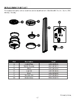
Page 17: ...0 643 0067 8 a m 8 p m EST Monday Sunday A Ceiling Plate A102 0365036 C Switch Housing A121 0470213 D Blade A141 0641030 E Light Kit A187 0516036 F Bowl A182 0502036 G Remote Unit A137 0540032 AA Blad...

Page 18: ......

Reviews: