


8
WIRING
INSTRUCTIONS
1
Hardware Used
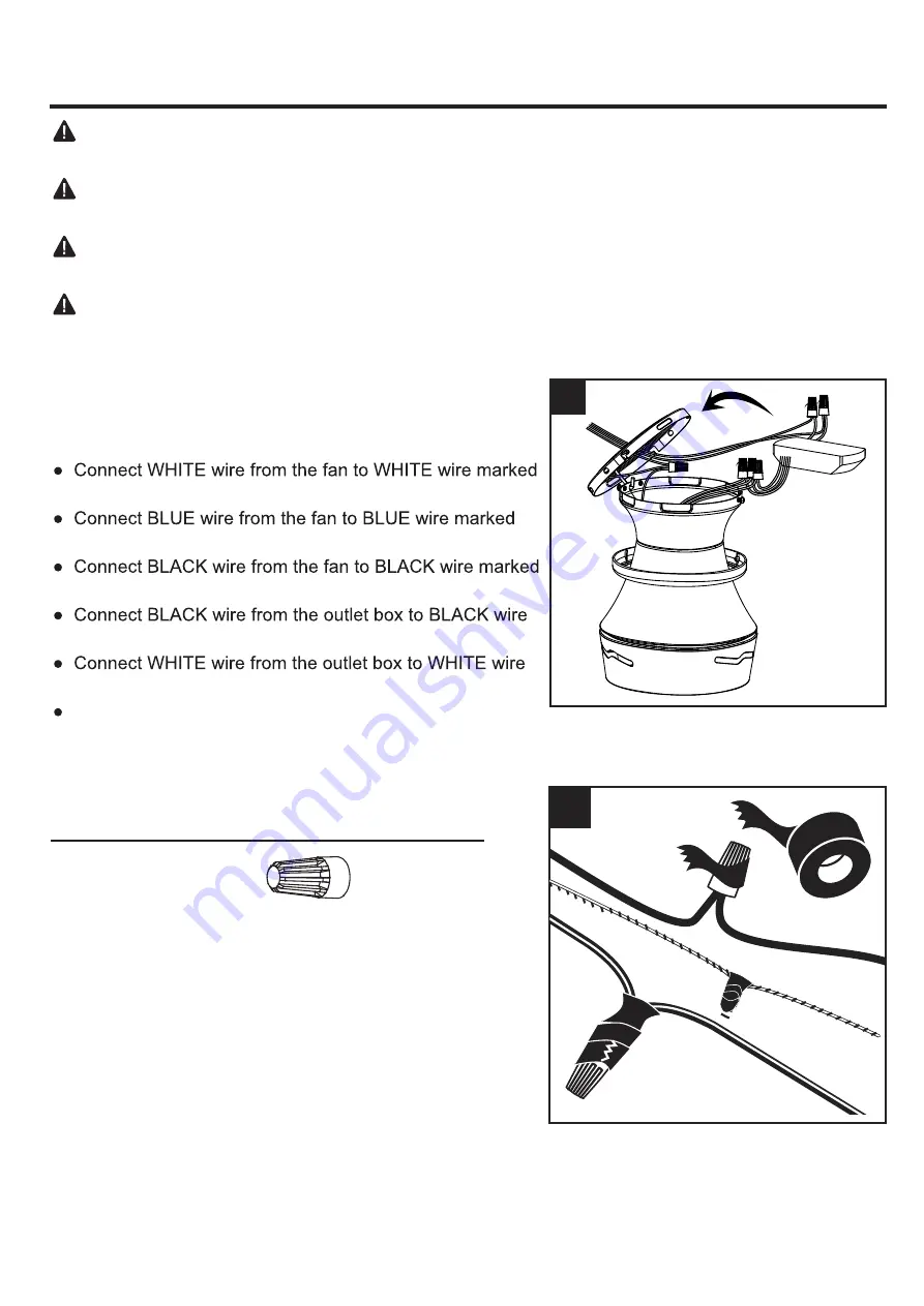
Wire Connector
x 6
2. Wrap electrical tape (not included) around each wire
connector and make sure no bare wire or wire strands
are visible after making connections. Then, turn wires
upward and carefully push them into the outlet box;
make sure the WHITE and GREEN connections are on
one side and the BLACK connections are on the other
side.
WARNING:
To avoid possible electrical shock, be sure electricity is turned off at the main fuse
box before hanging.
WARNING:
If you are not sure if the outlet box is grounded, contact a licensed electrician for
advice, as it must be grounded for safe operation.
WARNING:
If house wires are different colors than referred to in the following steps, stop
immediately. A professional electrician is recommended to determine proper wiring.
WARNING:
If you feel that you do not have enough electrical wiring knowledge or experience,
have your fan installed by a licensed electrician.
2
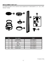
1. Follow steps below to wiring your fan, once wiring step
has been completed, slide the wired receiver into the
motor assembly (B) with the flat side of the receiver
facing the ceiling.
TO MOTOR N from the receiver.
FOR LIGHT from the receiver.
TO MOTOR L from the receiver.
marked AC IN L from the receiver.
marked AC IN N from the receiver.
Connect GROUND (GREEN) wires from ceiling plate
and fan assembly, to GROUND (GREEN or BARE
COPPER) from house.
Summary of Contents for HTD20005
Page 18: ......


