background image

OPERATIING INSTRUCTIONS

14

4

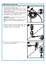
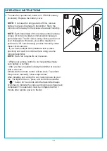
4. To make fan operational, install a 3V CR2032 battery 

    (included). Replace the battery cover. 


NOTE: 

If not used for long periods of time, remove 

    battery to prevent damage to transmitter. Store the 

    remote control away from excessive heat and humidity.


NOTE:

 Each transmitter of this remote control carries a 

    unique ID code to facilitate communication between 

    paired devices. The ID code is set by factory and is not 

    user changeable. However, you will be required to 

    perform an “ID code learning” process manually under 

    these circumstances.

    • 

If you have multiple fans installed within a close

    proximity and want to control all fans using a same 

    remote transmitter.


NOTE: 

Each fan requires its own receiver.

    • 

When your remote control is not responding (make 

    sure battery is not flat)

    • 

After you have replaced a faulty transmitter or receiver 

    with a new one.

    Otherwise the remote control will not work. To perform 

    this process manually, follow steps below:

    After installing and wiring the unit, restore power to your 

    fan. The light will be on, press and hold the transmitter 

    “         ” button for 5 seconds until the transmitter beeps 

    five times to indicate the code learning process have been 

    completed. This operation must be completed within 1 

    minute after restore power to the fan.

Summary of Contents for HTE21091

Page 1: ...ore returning to your retailer call our customer service department at 888 251 1003 8 a m 8 p m EST Monday Sunday You could also contact us at partsplus lowes com or visit www lowespartsplus com AS212...

Page 2: ...tion Initial Installation Instructions Standard Angle Mounting Instructions Wiring Instructions Final Installation Instruction Operating Instruction Care and Maintenance Troubleshooting Limited Lifeti...

Page 3: ...1 K Remote Unit 1 O P M 1 Clevis Pin Preassembled on Downrod Assembly B Hairpin Clip Preassembled on Downrod Assembly B Coupling Screw Preassembled on Coupling O Coupling Preassembled on Motor Assemb...

Page 4: ...positioned so there is at least 1 64 ft between the bulb and any illuminated surface For supply connections if the conductor of a fan is identified as a grounded conductor then it should be connected...

Page 5: ...When the service disconnecting means cannot be locked securely fasten a prominent warning device such as a tag to the service panel Chemical Burn Hazard Keep batteries away from children This remote...

Page 6: ...ing angle is not steeper than 20 3 Check existing outlet box not included to ensure it is securely fastened to at least two points in a structural ceiling member and can support the full weight of the...

Page 7: ...ARD ANGLE MOUNTING INSTRUCTIONS 1 Place downrod assembly B through canopy C canopy cover D and coupling cover E Feed power wires from motor assembly F through downrod assembly B then insert downrod as...

Page 8: ...efully lift the assembly and rest the hanger ball of downrod assembly B on the mounting bracket A attached to the outlet box Be sure the groove in the hanger ball is lined up with the tab on the mount...

Page 9: ...PPER from house WARNING To avoid possible electrical shock be sure electricity is turned off at the main fuse box before hanging WARNING If you are not sure if the outlet box is grounded contact a lic...

Page 10: ...ockwise then tighten all screws securely 2 Raise canopy cover D over the mounting screws P visible in canopy C Rotate canopy cover D clockwise until it locks into place You may need to adjust the moun...

Page 11: ...yhole slots from the switch housing H onto the two protruding mounting screws Q heads 6 Adjust the switch housing H until the screw heads are aligned with the keyholes then re install the mounting scr...

Page 12: ...d keep for later use 7 8 Attach the connector from light kit I to the connector from the motor assembly Align three holes on the light kit I and the switch housing H Re install the switch housing scre...

Page 13: ...hot air from the ceiling Push the switch RIGHT and see a SNOWFLAKE icon WARNING Turn off and wait for fan to stop before flipping the reverse switch Note Use a small screwdriver or ballpoint pen to m...

Page 14: ...hese circumstances If you have multiple fans installed within a close proximity and want to control all fans using a same remote transmitter NOTE Each fan requires its own receiver When your remote co...

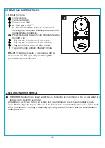
Page 15: ...blades for added protection OPERATING INSTRUCTIONS 5 Remote functions Turn speed up Turn speed down Turn fan ON OFF a Turn light ON OFF b Press and hold the button to start circular dimming the trans...

Page 16: ...screw in motor coupling is loose 4 Raise motor coupling up and tighten set screws securely 5 Blade is loose 5 Check that all blades are screwed firmly into blade holders Fan sounds noisy Fan wobbles...

Page 17: ...hanges in brass finish rusting pitting tarnishing corroding or peeling Brass finish fans maintain their beauty when protected from varying weather conditions The duration of any implied warranty which...

Page 18: ...device pursuant to part 15 of the FCC Rules These limits are designed to provide reasonable protection against harmful interference in a residential installation The remote control generates uses and...

Page 19: ...ou could also contact us at partsplus lowes com or visit www lowespartsplus com A Mounting Bracket A102 0406084 A103 0328401 A101 0141401 A108 0013401 A106 0489401 A141 0683001 A188 0423401 A187 05450...

Reviews: