background image

1

Serial Number

Purchase Date

ATTACH YOUR RECEIPT HERE

Questions, problems, missing parts?

 Before returning to your retailer, call our customer 

service department at 888-251-1003, 8 a. m. -- 8 p.m., EST, Monday -- Sunday. You could
also contact us at partsplus@lowes.com

SS23242

HARBOR BREEZE and logo design are 
trademarks or registered trademarks of 
LF, LLC. All rights reserved.

Español p. 21

BRACKENRIDGE FAN

ITEM #  5249295

MODEL #  HTE22025

Summary of Contents for HTE22025

Page 1: ...ur retailer call our customer service department at 888 251 1003 8 a m 8 p m EST Monday Sunday You could also contact us at partsplus lowes com SS23242 HARBOR BREEZE and logo design are trademarks or...

Page 2: ...ion Initial Installation Instructions Standard Angle Mounting Instructions Wiring Instructions Final Installation Instructions Operating Instructions Care and Maintenance Troubleshooting Limited Lifet...

Page 3: ...on Downrod Assembly B Mounting Bracket Screw preassembled on Mounting Bracket A Coupling Screw preassembled on Coupling L Downrod Assembly 1 2 Canopy Cover 1 2 1 1 Blade 3 1 Coupling preassembled on...

Page 4: ...ositioned so there is at least 1 64 ft between the bulb and any illuminated surface For supply connections if the conductor of a fan is identified as a grounded conductor then it should be connected t...

Page 5: ...5 WARNING CAUTION PREPARATION Estimated Assembly Time...

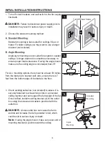
Page 6: ...ded to ensure it is securely fastened to at least two points in a structural ceiling member and can support the full weight of the fan Once verified install mounting bracket A to the outlet box using...

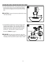
Page 7: ...RD ANGLE MOUNTING INSTRUCTIONS 1 Place downrod assembly B through canopy C canopy cover D and coupling cover E M B N L O Feed power wires from motor housing G through downrod assembly B then insert do...

Page 8: ...ire 4 Carefully lift the assembly and rest the hanger ball of downrod assembly B on the mounting bracket A attached to the outlet box Be sure the groove in the hanger ball is lined up with the tab on...

Page 9: ...IGHT from the receiver ORANGE ORANGE 1 To sync the remote from remote unit K to the receiver also in remote unit K first remove the battery cover from the remote and slide code switches to your choice...

Page 10: ...hen turn wires upward and carefully push them into the outlet box make sure the WHITE and GREEN connections are on one side and the BLACK connections are on the other side 4 4 Once wiring step has bee...

Page 11: ...cover D over the mounting screws P visible in canopy C Rotate canopy cover D clockwise until it locks into place You may need to adjust the mounting screws P until the canopy C and canopy cover D have...

Page 12: ...m the switch housing H onto the two protruding mounting screw heads 4 Remove one of the mounting screws on mounting plate of motor housing then loosen the other two 5 Keyslot Hole H Mounting Screws Mo...

Page 13: ...ck wire to black wire and white wire to white wire 7 Remove one of the screws on switch housing H then loosen the other two 7 I G Screws loosen only Screw remove H 8 I 9 Attach the light kit I to the...

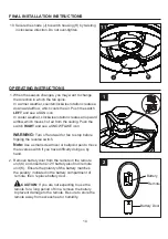
Page 14: ...RIGHT and see a SNOWFLAKE icon WARNING Turn off and wait for fan to stop before flipping the reverse switch Note Use a small screwdriver or ballpoint pen to move the reverse switch if you have difficu...

Page 15: ...as they were prior to the switch being turned OFF 3 Low speed Medium speed High speed Turn the fan off Turns both uplight and downlight on off Press and hold to achieve desired dimming setting for up...

Page 16: ...5 Blade is loose 5 Check that all blades are screwed firmly into blade holders Fan sounds noisy Fan wobbles TROUBLESHOOTING PROBABLE CAUSE CORRECTIVE ACTION PROBLEM 16 6 Blade holders are loose 6 Chec...

Page 17: ...changes in brass finish rusting pitting tarnishing corroding or peeling Brass finish fans maintain their beauty when protected from varying weather conditions The duration of any implied warranty whic...

Page 18: ...device pursuant to part 15 of the FCC Rules These limits are designed to provide reasonable protectionagainst harmful interference in a residential installation The remote control generates uses and...

Page 19: ...at partsplus lowes com A Mounting Bracket Canopy Downrod Assembly Canopy Cover Coupling Cover Blade Switch Housing Shade Light Kit Remote Unit Blade Screw A102 0084184 A101 0137036 A103 0328084 A108 0...

Page 20: ......

Reviews: