9
FINAL INSTALLATION
(continued from previous page)
Fig. 3
FAN OPERATION
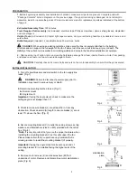
1.
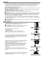
The fan pull chain, labeled SPEED on the switch housing (E),
has four positions to control fan speed. One pull is HIGH, two pulls
is MEDIUM, three is LOW and four turns the fan OFF. [Fig. 1]
2.
Pull the light pull chain, labeled LIGHT on the switch housing
(E), to turn the lights ON or OFF. [Fig. 2]
Fig. 3A
Fig. 3B
Fig. 1
Fig. 2
E
E
E
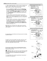
10.
Pull chain extensions (S) supplied in one of the hardware
packs or custom pull chain extensions (not included) may be
attached to fan and light pull chains. [Fig. 10]
NOTE:
This fan is remote control adaptable (remote control not
included). Any remote control used with this fan MUST be UL-
approved for DAMP LOCATIONS.
Fig. 10
S
D
S
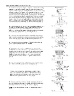
9.
Install four candelabra base 40 watt max. bulbs (X) included.
[Fig. 9]
Important:
When replacing bulbs, allow bulb(s) and glass
shade(s) to cool before touching them.
X
E
I
Fig. 9
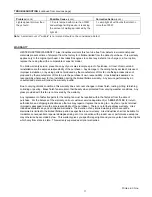
3.
Use the fan reverse switch, located on the switch housing (E), to
optimize your fan for seasonal performance. [Fig. 3] A ceiling fan will
allow you to raise your thermostat setting in summer and lower your
thermostat setting in winter without feeling a difference in your
comfort.
Note:
Wait for fan to stop before moving the reverse switch.
3A.
In
warmer
weather,
counterclockwise
movement of the fan
will result in downward airflow creating a wind chill effect. [Fig.
3A]
3B.
In
cooler
weather,
clockwise
movement of the fan will
result in upward airflow that can help move stagnant, hot air off
the ceiling area. [Fig. 3B]


