background image

Español p. 17

KITSILANO 

CEILING FAN

ITEM #1158773

MODEL #00960

Serial Number

Purchase Date

Harbor Breeze

®

 is a registered trademark of LF, 

LLC. All Rights Reserved.

Questions, problems, missing parts?

 Before returning to your retailer, call our 

customer service department at 1-866-473-4537, 8 a.m. - 6 p.m., EST, Monday - 

Thursday, 8 a.m. - 5 p.m., EST Friday 

PH18860

ATTACH YOUR RECEIPT HERE

UL MODEL #52-KITS

1

Summary of Contents for KITSILANO

Page 1: ...or Breeze is a registered trademark of LF LLC All Rights Reserved Questions problems missing parts Before returning to your retailer call our customer service department at 1 866 473 4537 8 a m 6 p m EST Monday Thursday 8 a m 5 p m EST Friday PH18860 ATTACH YOUR RECEIPT HERE UL MODEL 52 KITS 1 ...

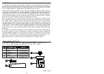
Page 2: ... 14 Care and Maintenance 15 Troubleshooting 15 Warranty 16 Replacement Parts List 16 PACKAGE CONTENTS PART DESCRIPTION QUANTITY A Mounting Bracket preassembled to canopy B 1 B Canopy 1 C Downrod Assembly 1 D Fan Motor Assembly 1 E Blade Arm 5 F Blade 5 G Light Fitter Assembly 1 H Bowl Cap 1 I Bulb 2 J Glass 1 K Remote Pack 1 L Lead Wire 1 3 2 K F A I D C B E J L H G ...

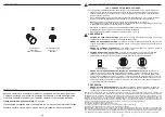
Page 3: ...f personal injury do not bend the blade brackets when installing the brackets balancing the blades or cleaning the fan DO NOT insert foreign objects in between the rotating fan blades FIRE ELECTRIC SHOCK OR PERSONAL INJURY HAZARD To reduce the risk of fire electric shock or personal injury mount to an outlet box marked ACCEPTABLE FOR FAN SUPPORT OF 35 1 lbs OR LESS and use the mounting screws prov...

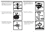
Page 4: ... the four screws on the top of the canopy B Remove the two non slotted screws and save 7 6 4 Install the mounting bracket A to the outlet box not included using the two screws provided with the outlet box Securely tighten the two screws 1 Outlet box A 4 Clip Pin C 5 B D C 6a Rubber insert and screw D 2 A B Loosen but do not remove Remove and save 3 ASSEMBLY INSTRUCTIONS 5 Remove pin and clip from ...

Page 5: ...mounting bracket A Push up to engage the slots and turn clockwise to lock in place Immediately tighten the two screws that were previously removed step 3 page 6 to fully secure the canopy B to the mounting bracket A AA 2 Outlet box Screw B 1 2 Twist wire ends together and screw wire connectors AA on in a clockwise direction Tape wire connectors AA and wires together with electrical tape not includ...

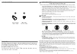
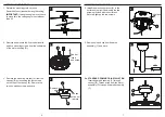
Page 6: ... switch cover on the light kit G BB E F 2 D 3 Screw G 4 Hardware Used Blade Screw x 15 BB 5 Connect the adapter plug of the BLUE wire from the fan motor assembly D to the adapter plug of the BLACK wire from the light kit G and connect the adapter plug of the WHITE wire from the fan motor assembly D to the adapter plug of the WHITE wire from the light kit G D White Black Blue G 5 FINAL INSTALLATION...

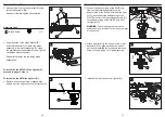
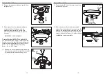
Page 7: ...at 1 866 473 4537 8 a m 6 p m EST Monday Thursday 8 a m 5 p m EST Friday FINAL INSTALLATION Hex Nut Switch housing cover 10 10 Remove the hex nut preassembled inside the switch housing cover of the light fitter assembly G and detach the switch housing cover XX Switch housing cover Switch housing cover plug special order 11 Screw D 12 11 Press the plug XX into the center hole of the switch housing ...

Page 8: ...ning any maintenance Do not use water or detergents when cleaning the fan or fan blades A dry dust cloth or lightly dampened cloth will be suitable for most cleaning Clean fan housing with only a soft brush or lint free cloth to avoid scratching the finish Clean blades with a lint free cloth You may occasionally apply a light coat of furniture polish to blades for added protection At least twice a...

Page 9: ...sh rusting pitting tarnishing corroding or peeling Brass finish fans maintain their beauty when protected from varying weather conditions Any glass provided with this fan is not covered by this warranty Any replacement of defective parts for the ceiling fan must be reported within the first year from the date of purchase For the balance of the warranty call our customer service department at 1 866...

Page 10: ... registrada de LF LLC Todos los derechos reservados Preguntas problemas piezas faltantes Antes de volver a la tienda llame a nuestro Departamento de Servicio al Cliente al 1 866 473 4537 de lunes a jueves de 8 a m a 6 p m y los viernes de 8 a m a 5 p m hora estándar del Este ADJUNTE SU RECIBO AQUÍ MODELO UL 52 KITS 17 ...

Page 11: ...e problemas 31 Garantía 32 Lista de piezas de repuesto 32 CONTENIDO DEL PAQUETE PIEZA DESCRIPCIÓN CANTIDAD A Soporte de montaje preensamblado en la base B 1 B Base 1 C Ensamble de la varilla 1 D Ensamble del motor del ventilador 1 E Brazo del aspa 5 F Aspa 5 G Ensamble del soporte de iluminación 1 H Tapa de la pantalla 1 I Bombilla 2 J Pantalla de vidrio 1 K Paquete remoto 1 L Cable conductor 1 19...

Page 12: ...lesiones personales no doble las abrazaderas de las aspas al instalar las abrazaderas equilibrar las aspas o limpiar el ventilador NO coloque objetos extraños entre las aspas en movimiento del ventilador RIESGO DE LESIONES PERSONALES INCENDIO O DESCARGA ELÉCTRICA para reducir el riesgo de incendio descargas eléctricas o lesiones personales instale el ventilador en una caja de salida que esté marca...

Page 13: ...s de la parte superior de la base B Retire los dos tornillos sin ranura y guárdelos 23 22 4 Instale el soporte de montaje A en la caja de salida no se incluye con los dos tornillos que se incluyen con la caja de salida Apriete firmemente los dos tornillos 1 Caja de salida A 4 Sujetador Pasador C 5 B D C 6a Accesorio de goma y tornillo D 2 A B Suelte pero no retire Retire y guarde 3 INSTRUCCIONES D...

Page 14: ...gírelas en dirección de las manecillas del reloj para bloquearlas en su lugar Apriete inmediatamente los dos tornillos que retiró previamente paso 3 pág 6 para asegurar la base B al soporte de montaje A AA 2 Caja de salida Tornillo B 1 2 Gire los extremos de los conductores para unirlos y enrosque los conectores de alambres AA en dirección de las manecillas del reloj Una los conectores de alambres...

Page 15: ... iluminación G BB E F 2 D 3 Tornillo G 4 Aditamentos utilizados Tornillo del aspa x 15 BB 5 Conecte el enchufe del adaptador del conductor AZUL del ensamble del motor del ventilador D al enchufe del adaptador del conductor NEGRO del kit de iluminación G y conecte el enchufe del adaptador del conductor BLANCO del ensamble del motor del ventilador D al enchufe del adaptador del conductor BLANCO del ...

Page 16: ...e y los viernes de 8 a m a 5 p m hora estándar del Este INSTALACIÓN FINAL Tuerca hexagonal Cubierta de la carcasa del interruptor 10 10 Retire la tuerca hexagonal preensamblada dentro de la cubierta de la carcasa del interruptor del ensamble del soporte de luz G y retire la cubierta de la carcasa del interruptor XX Cubierta de la carcasa del interruptor Enchufe de la cubierta de la carcasa del int...

Page 17: ...principal No utilice agua ni detergentes para limpiar el ventilador o las aspas Se recomienda utilizar un paño suave y seco o un paño levemente humedecido para limpiar el producto Limpie la carcasa del ventilador solo con un cepillo suave o con un paño sin pelusas para evitar que se raye el acabado Limpie las aspas con un paño sin pelusas De vez en cuando puede aplicar una fina capa de pulidor par...

Page 18: ...ido picaduras deslustre corrosión o descascarado Los ventiladores con acabado de latón mantienen su belleza cuando se los protege de las condiciones climáticas cambiantes La garantía no cubre los elementos de vidrio incluidos con este ventilador Cualquier reemplazo de piezas defectuosas para el ventilador de techo debe informarse dentro del primer año a partir de la fecha de compra Para conocer el...

Reviews: