background image

WIRING INSTRUCTIONS

11

Lowes.com/harborbreeze

FINAL INSTRUCITONS 

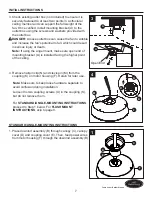
3.  Wrap electrical tape (not included) around each wire 

     connector and make sure no bare wire or wire strands 

     are visible after making connections.  

Then, turn wires upward and carefully push them into 

the outlet box; make sure the WHITE and GREEN 

connections are on one side and the BLACK connections 

are on the other side.

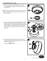
1. Loosen (but do not remove) the two mounting bracket 

    screws (L) preassembled on mounting bracket (A) that 

    align with the slotted holes on canopy (C). Remove the 

    other two mounting bracket screws (L).

Lift canopy (C) up so slotted holes engage loosened 

screw heads on mounting bracket (A), then twist canopy 

(C) clockwise. Re-install previously removed mounting 

bracket screws (L), then tighten all screws securely.

Note:

 If the canopy cover (D) is loosen during installation, 

please press it to the inner edge of the canopy (C). 

2

H

G

BB

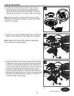
2. Position one blade iron (G) under blade (H). Insert three 

    blade screws (BB) through blade (H) and into blade iron 

    (G). Tighten each blade screw (BB) evenly, starting with 

    the center screw. Repeat for the remaining blade 

    assemblies. 


Note: 

Flushmount installation will not use the downrod assembly (B) or canopy cover (D).

Hardware Used

 Blade Screw

x 15

BB

3

BLACK

BLUE

WHITE

GREEN

Outlet Box

AA

1

A

C

L

C

D

Summary of Contents for L1305

Page 1: ...ns problems missing parts Before returning to your retailer call our customer service department at 1 800 643 0067 8 a m 6 p m EST Monday Thursday 8 a m 5 p m EST Friday EB14428 ATTACH YOUR RECEIPT HE...

Page 2: ...nitial Instructions Standard Angle Mounting Instructions Flushmount Instructions Wiring Instructions Final Instructions Operating Instructions Care and Maintenance Troubleshooting Limited Lifetime War...

Page 3: ...Coupling K 1 D Canopy Cover preassembled on Canopy C 1 N Hairpin Clip preassembled on Coupling K 1 E Coupling Cover 1 O Coupling Screw preassembled on Coupling K 2 F Motor Housing 1 P Balance Kit 1 G...

Page 4: ...etermine the correct type and electrical rating required The lighting fixture must be positioned so there is at least 1 64 ft between the bulb and any illuminated surface Be careful not to damage or c...

Page 5: ...lation which could cause serious injury or death from electric shock Before beginning assembly of product make sure all parts are present Compare parts with package contents list and hardware contents...

Page 6: ...angled or vaulted ceilings A longer downrod is sometimes necessary to ensure proper blade clearance If using the angle mount make sure the ceiling angle is not steeper than 20 C Flush Mounting Flushm...

Page 7: ...E D B 1 F 3 Check existing outlet box not included to ensure it is securely fastened to at least two points in a structural ceiling member and can support the full weight of the fan Once verified ins...

Page 8: ...lift the assembly and rest the hanger ball of downrod assembly B on the mounting bracket A attached to the outlet box Be sure the groove in the hanger ball is lined up with the tab on the mounting br...

Page 9: ...near the coupling K on the motor housing F Save them for future use Guide motor wires through the base of the canopy C then attach canopy C to motor housing F with previously removed screws Tighten se...

Page 10: ...f you are not sure if the outlet box is grounded contact a licensed electrician for advice as it must be grounded for safe operation 1 Connect the GREEN wires from the hanger ball of downrod assembly...

Page 11: ...er two mounting bracket screws L Lift canopy C up so slotted holes engage loosened screw heads on mounting bracket A then twist canopy C clockwise Re install previously removed mounting bracket screws...

Page 12: ...F 12 Lowes com harborbreeze Motor Screw 5 Insert the wires from the motor housing F through the middle hole in the switch housing I Attach the switch housing I to the mounting plate on motor housing...

Page 13: ...Note To install the fan with the light kit proceed to installation instruction with optional light kit 13 Lowes com harborbreeze 8 Assemble fob DD the fan pull chain 8 Hardware Used Fob x 1 DD DD R I...

Page 14: ...ush the switch on switch cover J to RIGHT and see a SNOWFLAKE icon 2 At least twice each year tighten all screws and lower canopy to check mounting plate screws Clean fan housing with only a soft brus...

Page 15: ...Tighten the set screw in the downrod assembly 3 Fan hanger ball is not properly seated in canopy tabs 3 Turn power off support the fan very carefully and check that the hanger ball is properly seated...

Page 16: ...connection in the switch housing 3 Motor reversing switch not engaged 3 Push switch firmly right or left Fan will not operate when switch is in the middle 4 Pull chain switch not on 4 Pull switch cha...

Page 17: ...not cover changes in brass finish rusting pitting tarnishing corroding or peeling Brass finish fans maintain their beauty when protected from varying weather conditions NOTE A small amount of wobble i...

Page 18: ...ion Part A Mounting Bracket A102 0132070 B Downrod Assembly A103 0156346 C Canopy A101 0347346 D Canopy Hole Cover A108 0260346 E Coupling Cover A106 0198346 G Blade Iron A143 0199346 H Blade A141 036...

Reviews: