background image

15

OPERATING INSTRUCTIONS

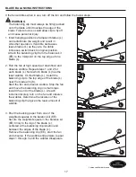
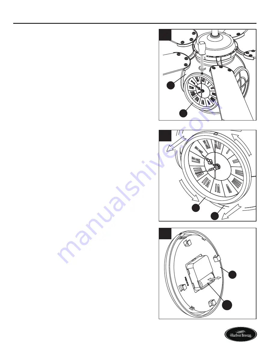
6. To install/replace the clock battery, remove the 

     preassembled screw in the clock assembly 

    (M) from housing assembly (G). Retain the 

     screw for later.  

7. Twist the clock assembly (M) counterclockwise 

     to remove it from housing assembly (G).

8. Install the battery (FF) into the clock assembly 

    (M). If replacing battery (FF), use a 1.5-volt AA 

    battery.

Lowes.com/harborbreeze

  If you are not expecting to use the clock for a 

  long period of time, remove the battery to 

  prevent damage to the item.


CAUTION

M

7

G

M

FF

8

6

M

G

Summary of Contents for LP8210LAZ

Page 1: ...a registered trademark of LF LLC All Rights Reserved Questions problems missing parts Before returning to your retailer call our customer service department at 1 888 567 2055 8 a m 5 p m EST Monday F...

Page 2: ...re Contents Safety Information Preparation Assembly Instructions Wiring Instructions Final Assembly Instructions Operating Instruction Blade Balancing Instructions Care and Maintenance Troubleshooting...

Page 3: ...ION QUANTITY I J K L M N Bulb Remote Blade Arm Blade Clock Assembly preassembled to Housing Assembly G Receiver Unit preassembled to Motor Assembly A A B C D E F G H Motor Assembly Hanger Bracket Down...

Page 4: ...nections are secure to prevent the fan from falling For supply connections if the conductor of a fan is identified as a grounded conductor then it should be connected to a grounded conductor power sup...

Page 5: ...lass A digital device statements of 15 105 a must be included when appropriate for the device in question Lowes com harborbreeze WARNING Do not install or use fan if any part is damaged or missing To...

Page 6: ...ssembled pin from the downrod C then remove the hanger ball Retain the pin and hanger ball for later 2 Remove the preassembled hairpin clip and clevis pin from the bottom of downrod C Retain the pin a...

Page 7: ...blades L are fully seated against the blade arms K Install and tighten the washer head screws BB with fiber washers CC to secure the blades L to the blade arms K Lowes com harborbreeze WARNING It is...

Page 8: ...h the two holes in the downrod C and align the hanger ball so the pin is captured in the groove in the top of the hanger ball Pull the hanger ball up tight against the pin Securely tighten the preasse...

Page 9: ...ed for safe operation WARNING To avoid possible electrical shock be sure electricity is turned off at the main fuse box before hanging WARNING The fan must hang with at least 7 ft of clearance from th...

Page 10: ...n Wire from Hanger Bracket Ground Green Wire from Hanger Ball Ground Listed Outlet Box Household Supply Black Wire from Supply Black Wire from Fan 2 After connections have been made turn leads upward...

Page 11: ...ottom of the motor assembly A Slightly loosen the remaining three screws Assemble the housing assembly G to the adaptor plate of the motor assembly A using the three keyslots in the housing assembly G...

Page 12: ...turning the electricity on at the main fuse box 1 ON ON ON ON ON ON ON ON FINAL ASSEMBLY INSTRUCTIONS 4 Install bulb I 5 Securely attach glass H by twisting clockwise onto the housing assembly G 5 H G...

Page 13: ...st press the SET button within 60 seconds of restoring power to the fan c The fan will start to run and begin the control setting process The fan will run in both directions for a total of approximate...

Page 14: ...han CFL The D selection is to be used with CFLs as CFLS cannot be dimmed The receiver provides the following protective function Lock position The DC motor has a built in safety feature against blade...

Page 15: ...for later 7 Twist the clock assembly M counterclockwise to remove it from housing assembly G 8 Install the battery FF into the clock assembly M If replacing battery FF use a 1 5 volt AA battery Lowes...

Page 16: ...RATING INSTRUCTIONS 9 Reinstall the clock assembly M into the housing assembly G by twisting it clockwise 10 Re insert the previously removed screw into the clock assembly M and housing assembly G tig...

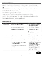
Page 17: ...until the wobble disappears BLADE BALANCING INSTRUCTIONS 2 Run the fan at high speed air down ow and observe wobble Repeat steps 1 and 2 for each blade L Note which blade L has the least wobble On th...

Page 18: ...t attached to fan 2 Loose screws in motor housing 3 Screws securing fan blade arms to motor hub are loose Lowes com harborbreeze WARNING Do not use water when cleaning the ceiling fan It could damage...

Page 19: ...tion of fan blades can redistribute the weight and result in a smoother operation For example exchange blades in positions 1 and 3 or 1 and 4 If this does not improve wobble exchange 2 and 4 or 2 and...

Page 20: ...tions so that we may repair or replace the ceiling fan Any fan or parts returned improperly packaged is the sole responsibility of the purchaser There is no further expressed warranty The manufacturer...

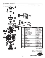
Page 21: ...ADRAC8GT1 6LAZ PPAC1005LAZ APPAC1101LAZ AP821001LAZ P821004LAZ AP821009FW PPE27C23 TR29WH AP821014LAZ AP821005WACY AP821017 RECAN125S HDWBH8210BL HDWBM8210BL HDWBM8210BL HDWWNUTS4 LBALKT HDWHW8210 PA...

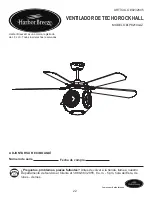
Page 22: ...VENTILADOR DE TECHO ROCK HALL ART CULO 0232645 MODELO LP8210LAZ ADJUNTAR SU RECIBO AQU N mero de serie Fecha de compra Preguntas problemas piezas faltantes Antes de volver a la tienda llame a nuestro...

Page 23: ...Instrucciones de ensamblaje Instrucciones de cableado Instrucciones de ensamblaje finales Instrucciones de funcionamiento Instrucciones para balancear las aspas Cuidado y mantenimiento Soluci n de pr...

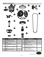
Page 24: ...illo de la base Cubierta para el acoplador del motor Ensamble de carcasa Vidrio PIEZA DESCRIPCI N CANTIDAD A B C D E F G H 1 1 1 1 1 1 Bombilla Control remoto de mano Brazo del aspa Aspa Ensamble del...

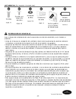
Page 25: ...ean seguras a fin de evitar que se caiga En lo que respecta a las conexiones de suministro si el conductor del ventilador est identificado como conductor con conexi n a tierra se le debe conectar a un...

Page 26: ...res secos Lea todas las instrucciones y la informaci n de seguridad antes de instalar el nuevo ventilador Revise los diagramas de ensamblaje adjuntos PRECAUCI N Nota Tras someterlo a las pruebas corre...

Page 27: ...ente ensamblar el producto si falta alguna pieza o si stas est n da adas Tiempo estimado de ensamblaje 60 minutos Herramientas necesarias para el ensamblaje no se incluyen Destornillador Phillips dest...

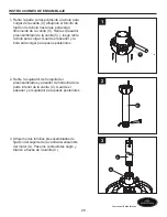
Page 28: ...pasador y la bola para colgar para pasos posteriores 2 Retire la sujetador de horquilla del preensamblados y pasador de horquilla de la parte inferior de la varilla C Guarde el pasador y el sujetador...

Page 29: ...aspa Instale y apriete los tornillos con cabeza BB junto con las arandelas de fibra CC para asegurar las aspas L a los brazos del aspa K Lowes com harborbreeze ADVERTENCIA Es fundamental que instale...

Page 30: ...a colgar de manera tal que el pasador quede inserto en la ranura de la parte superior de la bola para colgar Sujete la bola para colgar firmemente al pasador Fije bien el tornillo preensamblados de fi...

Page 31: ...tar la alimentaci n el ctrica de la caja de fusibles principal antes de colgar el ventilador ADVERTENCIA ADVERTENCIA Debe colgar el ventilador a una distancia m nima de 2 13 m desde las aspas hasta el...

Page 32: ...homologada Suministro el ctrico Conductor negro del suministro Conductor negro del ventilador C B Conecte el conductor verde del ensamble de la varilla C y el conductor verde con puesta a tierra de l...

Page 33: ...nsamble del motor A Afloje ligeramente los tres tornillos restantes Coloque el ensamble de la ensamble de carcasa G en el ensamble de la ensamble del motor A usando los tres chaveteros del ensamble de...

Page 34: ...cidad de la caja de fusibles principal 1 ON ON ON ON ON ON ON ON INSTRUCCIONES DE ENSAMBLAJE FINALES 4 Instale la bombilla I 5 Fije firmemente el vidrio H gir ndolo en direcci n de las manecillas del...

Page 35: ...da e el control remoto Aseg rese de almacenar el control remoto alejado del calor y humedad extremos PRECAUCI N b Tras instalar la unidad y restaurar la electricidad a su ventilador mantenga puls ado...

Page 36: ...segundos de interrupci n Extraiga los obst culos antes de restaurarlo Protecci n sobre 80 W Cuando el receptor detecta que el consumo de electricidad del motor supera los 80 vatios la fuente de alimen...

Page 37: ...oj M en direcci n contraria a las manecillas del reloj para retirarlo del ensamble de la carcasa G 8 Instale la bater a FF en el ensamble del reloj M Cuando cambie la bater a FF use una de tipo AA de...

Page 38: ...nstalar el ensamble del reloj M en el ensamble de la carcasa G gir ndolo en direcci n de las manecillas del reloj 10 Vuelva a colocar el tornillo que retir anteriormente en el ensamble del reloj M y e...

Page 39: ...observe el tambaleo Repita los pasos 1 y 2 para cada aspa L Tenga en cuenta qu aspa L tiene el menor tambaleo Instale en dicha aspa L el sujetador de equilibrio en el borde superior del aspa L cerca...

Page 40: ...polvo de las aspas peri dicamente Lo ideal es usar un plumero de plumas Evite usar agua limpiadores o trapos speros ya que pueden combar y arruinar el acabado Sustituci n de las bombillas Utilice E 27...

Page 41: ...rrectamente 4 Compruebe que los soportes de las aspas del ventilador est n firmes y uniformemente asentados en la superficiede la carcasa del motor Si los soportes no est n bien asentados afloje los t...

Page 42: ...corrosi n o descascaramiento Los ventiladores con acabado de lat n mantienen su belleza cuando se les protege de las cambiantes condiciones atmosf ricas La garant a no cubre los elementos de vidrio in...

Page 43: ...AZ APGAC110RBL ADRAC8GT1 6LAZ PPAC1005LAZ APPAC1101LAZ AP821001LAZ P821004LAZ AP821009FW PPE27C23 TR29WH AP821014LAZ AP821005WACY AP821017 RECAN125S HDWBH8210BL HDWBM8210BL HDWBM8210BL HDWWNUTS4 LBALK...

Reviews: