background image

1

ATTACH YOUR RECEIPT HERE

Purchase Date ___________________________

Questions, problems, missing parts?

 Before returning to your retailer, call our customer 

service department at  1-800-643-0067, 8 a.m. - 8 p.m., EST, Monday - Sunday.

Harbor Breeze® is a registered trademark  

of LF, LLC. All Rights Reserved.

VR20328

ITEM #1024423, 1461048, 2758997

MERRIMACK II CEILING FAN 

MODEL #41125, 42073, 42241

Español p. 23

H

arbor Breez

e

H

arbor Breez

e

LISTED FOR 

DAMP LOCATION

Summary of Contents for MERRIMACK II 41125

Page 1: ...ur retailer call our customer service department at 1 800 643 0067 8 a m 8 p m EST Monday Sunday Harbor Breeze is a registered trademark of LF LLC All Rights Reserved VR20328 ITEM 1024423 1461048 2758...

Page 2: ...mation 5 Preparation 6 Initial Installation 7 Standard or Angle Mounting Instructions 9 Closemount Instructions 11 Wiring 12 Final Installation 13 Operating Instructions 18 Care and Maintenance 19 Tro...

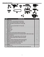
Page 3: ...otor Assembly N 2 M Phillips Head Closemount Screws preassembled to Motor Assembly N 3 N Motor Assembly 1 O Fitter Plate Screw preassembled to Fitter Plate P 3 P Fitter Plate preassembled to Motor Ass...

Page 4: ...E CONTENTS shown actual size Wire Connector Qty 3 1 extra Blade Screw Qty 15 1 extra Blade Washer Qty 15 1 extra Pull Chain Extension Qty 2 Motor Screw 1 extra AA BB CC DD XX H arbor Bree z e H arbor...

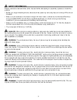
Page 5: ...loud humming noise from the fan To reduce the risk of fire or electric shock do NOT use a full range dimmer switch to control the fan speed WARNING To reduce the risk of fire electric shock or persona...

Page 6: ...f and on the user is encouraged to try to correct the interference by one or more of the following measures Reorient or relocate the receiving antenna Increase the separation between the equipment and...

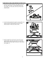
Page 7: ...mounting is best suited for angled or vaulted ceilings A longer downrod is sometimes necessary to ensure proper blade clearance Note If using the angle mount check to ensure the ceiling angle is not...

Page 8: ...e outlet box CAUTION It is very important you use the proper hardware when installing the mounting bracket D as this will support the fan 6 Remove all 10 preassembled motor screws R and five preassemb...

Page 9: ...e at the top of the motor assembly N 2 Insert the downrod A through the canopy E and yoke cover G Feed the wires from the motor assembly N through the downrod A 3 Slide the downrod A into the yoke of...

Page 10: ...om the end of the white wire Twist the stripped ends of each strand of wire within the insulation with pliers not included Repeat this step for black and blue wires Note If you did not cut back the le...

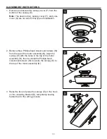
Page 11: ...e Phillips head closemount screws M from the top of the motor assembly N Align the canopy E with the holes in the top of the motor assembly N then re install the Phillips head closemount screws M to s...

Page 12: ...om the fan to the Black hot supply wire Secure all wiring connections together with wire connectors AA Note If there is a second hot power wire coming from the outlet box connect it to the Blue light...

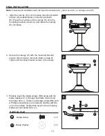
Page 13: ...page 8 Tighten all mounting bracket screws X securely 3 Partially insert the blade screws BB along with the blade washers CC through the blade K and into the blade arm J Tighten each blade screw BB w...

Page 14: ...plate P and save Loosen but do not remove the other two fitter plate screws O Note Make sure to keep loose hardware separate to avoid confusion during installation 6 Align the two key slots in the lig...

Page 15: ...ckets 8 Connect the 9 pin connector from the fitter plate P to the 9 pin connector from the light kit Q 9 Align the two key slots in the light kit Q with the two previously loosened light pan screws S...

Page 16: ...lass globe I over the threaded rod on light kit Q Lift the finial cap T up until it is flush with the glass bowl I and secure with the finial U 12 Align the three grooves on the inside of the light fr...

Page 17: ...3 Attach the pull chain extensions DD or custom pull chain extensions not included to the fan and light pull chains Hardware Used DD Pull Chain Extension x 2 14 Turn on power supply to the fan Assembl...

Page 18: ...er weather push the reverse switch to the right to display the snowflake icon which will result in upward airflow that can help move stagnant hot air off the ceiling area Important The reverse switch...

Page 19: ...sure the wall switch is turned on 3 Turn the power on or check the fuse breaker 4 Turn the power off and check all connections at the ceiling outlet box There is excessive wobbling 1 The blades and or...

Page 20: ...not use a full range dimmer switch to control the fan speed 4 Ensure the outlet box is secured to the building structure 5 Ensure the mounting bracket is secured to the outlet box and that the screws...

Page 21: ...to varying climate conditions this warranty does not cover any changes in plated finishes including rusting pitting corroding tarnishing or peeling Plated metals give their longest useful life when p...

Page 22: ...r 4L000008290 4L000009340 4L000011080 G Yoke Cover 4L000011330 4L000009350 4L000013880 H Light Pan 4L000011340 4L000009360 4L000013900 I Glass Globe 4L166850001 4L166850001 4L166850001 J Blade Arm 4L0...

Reviews: