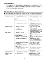
background image

11

TROUBLESHOOTING

Problem


Possible Cause


Corrective Action

Fan does not move.  

1. Reverse switch not engaged. 

1. Push switch firmly either right or left. 


2. Power is off or fuse is blown. 

2. Turn power on or check fuse.


3. Faulty wire connection. 

3. Turn power off. Loosen canopy (B) and  


check all connections.


4. Plugs not connected properly. 

4. 

Check that male and female plugs in


light kit fitter (G) are connected properly  


according to instructions on page 8.

Noisy operation.  

1. Blades (J) are loose. 

1. Tighten all blade screws (L). 


2. Cracked blade (J). 

2. Replace blade (J).


3. Fan is new. 

3. Allow fan a “break in” period of a few  


days, especially when running the fan at  


Medium and High speeds.
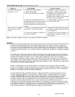
Excessive wobbling.  

1. Blades (J) are loose. 

1. Tighten all blade screws (L). 


2. Blade arms (I) incorrectly attached. 

2. Re-install blade arms (I).


3. Unbalanced blades (J). 

3. Switch one blade with a blade (J) from


the opposite side.


4. Fan not securely mounted. 

4. Turn power off. Carefully loosen


canopy (B) and verify that mounting


bracket (C) is secure.


5. Fan too close to vaulted ceiling. 

5. Use a longer downrod (A) or move fan


to another location.


6. Set screw(s) on motor housing yoke 

6. Tighten yoke set screw(s) securely.


is (are) not tightened properly.


7. Set screw on hanging ball is not 

7. Carefully loosen and lower canopy (B)


tightened properly. 

and verify that set screw on hanging ball


is tightened securely.

Fan operates but lights  

1. Bulbs not installed correctly. 

1. Re-install bulbs.

fails. 

2. Wires in canopy (B) not wired properly. 

2. Check wires in canopy (B) and, if


necessary, re-wire according to


instructions on page 7.


3. Wall switch to fan is off. 

3. Make sure that wall switch to fan is on.


4. Plugs not connected properly. 

4. 

Check that male and female plugs in


light kit fitter (G) are connected properly  


according to instructions on page 8.


5. Light kit is lamped with more than the 

5. Lamp light kit with bulbs that total no


allowable 190W, causing the wattage  

 more than 190W.


limiting device to interrupt the flow of 


electricity to the light kit.

Fan and lights fail to operate 

1. Learning process was not done correct-  1. Turn power off, remove battery cover

with remote control. 

ly and code was not activated. 

and repeat Steps 5 and 6 on page 9.


2. Battery in remote control transmitter (W)  2. Check battery in transmitter (W) and


is no longer good. 

replace battery if necessary.
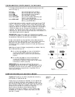
Note:

  A small amount of "wobble" is normal and should not be considered a defect.

WARNING: 

Before beginning work, shut off the power supply to avoid electrical shock.

Summary of Contents for MONTCLAIR E-CM54RBZ5CRCI

Page 1: ...evice or control fan speed with a full range dimmer switch WARNING To reduce the risk of fire electric shock or personal injury do not bend the blade arms when installing them balancing the blades or cleaning the fan Do not insert foreign objects between the rotating fan blades Mount to outlet box marked ACCEPTABLE FOR FAN SUPPORT and use mounting screws provided with the outlet box Most outlet bo...

Page 2: ...5 Initial Installation 5 Fan Mounting 6 Wiring for Remote Control and Fan 6 7 Final Installation 7 8 Automated Learning Process Activating Code 9 Remote Control and Fan Operation 9 10 Lighted Housing Bulb Replacement 10 Care and Maintenance 10 Troubleshooting 11 Warranty 12 ...

Page 3: ...t box Most outlet boxes commonly used for the support of lighting fixtures are not acceptable for fan support and may need to be replaced Consult a qualified electrician if in doubt Secure the box directly to the building structure The outlet box and its support must be able to support the moving weight of the fan at least 35 lbs Do NOT use a plastic outlet box 7 After you install the fan make sur...

Page 4: ...2 S Canopy Mounting Screw attached to mounting bracket 2 T Pin in motor housing yoke 1 U Clip attached to pin 1 V Remote Control Receiver 1 W Remote Control Transmitter 1 X Canopy Cover in hardware pack 1 Y Candelabra Base Bulb pre installed in lighted housing 6 Z 9 volt Battery in hardware pack 1 A B C D E F G H I J K L M N O P Q R S T U V W X Y NOTE For replacement parts call our customer servic...

Page 5: ...2 candelabra base 60 watt max bulbs included for light kit DANGER When using an existing outlet box make sure the outlet box is securely attached to the building structure and can support the full weight of the fan Failure to do this can result in serious injury or death The stability of the outlet box is essential in minimizing wobble and noise in the fan after installation is complete CAUTION Be...

Page 6: ...rod A and attach to the 12 in downrod A Insert downrod A through canopy B canopy cover X and yoke cover D Note Canopy cover X must be turned with the shiny side toward the motor housing E Thread wires from motor housing E through downrod A Fig 2 Note Black wire is hot power for fan Orange wire is hot power for lighted housing Blue wire is hot power for light kit White wire is common for fan and li...

Page 7: ...e side Fig 3 Note The remote control included with this fan meets the following requirements a Not for use with solid state fans b Electrical rating 120V 60 Hz motor amps 1 0 MAX light watts 300 incandescent only Fig 2 Q Q Q black black black from fan white white blue blue black supply wire ground green or bare white supply wire white AC IN N AC IN L V black white ground green or bare antenna from...

Page 8: ...otor screws K and lock washers N that were previously removed on page 5 Additional motor screws K and lock washers N are in hardware pack Insert only one motor screw K along with lock washer N through blade arm I to attach blade arm I to motor and partially tighten the motor screw K Repeat with remaining blade arms I Fig 3 Fig 2 2 Position blade arm I under blade J and secure blade arm I with scre...

Page 9: ... sliding code switches 1 through 4 to your choice of up or down position Factory setting is all up Do not use this position Use a small screwdriver or ballpoint pen to slide firmly up or down Fig 1 3 Locate dimmer switch to the right of the code switches labeled with a D and an X Fig 1 Set dimmer switch to the ON D position only if using incandescent bulbs Set dimmer switch to OFF X position if us...

Page 10: ...nd then tighten all screws on the fan Clean motor housing E with only a soft brush or lint free cloth to avoid scratching the finish Clean blades J with a lint free cloth You may occasionally apply a light coat of furniture polish to wood blades for added protection Important Shut off main power supply before beginning any maintenance Do not use water or a damp cloth to clean the ceiling fan LIGHT...

Page 11: ...en yoke set screw s securely is are not tightened properly 7 Set screw on hanging ball is not 7 Carefully loosen and lower canopy B tightened properly and verify that set screw on hanging ball is tightened securely Fan operates but lights 1 Bulbs not installed correctly 1 Re install bulbs fails 2 Wires in canopy B not wired properly 2 Check wires in canopy B and if necessary re wire according to i...

Page 12: ...nditions this warranty does not cover changes in brass finish rusting pitting tarnishing corroding or peeling Brass finish fans maintain their beauty when protected from varying weather conditions Any glass provided with this fan is not covered by the warranty Any replacement of defective parts for the ceiling fan must be reported within the first year from the date of purchase For the balance of ...

Page 13: ...n personal no doble los brazos de las paletas mientras las esté instalando ni cuando esté balanceando las paletas ni cuando esté limpiando el ventilador No inserte objetos extraños entre las paletas giratorias del ventilador Sujete a una caja de salida marcada Aceptable para sostener ventilador ACCEPTABLE FOR FAN SUPPORT en inglés y use los tornillos de montaje proporcionados con la caja de salida...

Page 14: ...entilador 18 Conexión de los cables del control remoto y el ventilador 19 Instalación final 20 21 Proceso de aprendizaje automático Activando el código 21 Funcionamiento del control remoto y el ventilador 22 Reemplazo de bombillas del bastidor iluminado 22 Cuidado y mantenimiento 23 Localización de fallas 23 24 Garantía 24 14 ...

Page 15: ...de las cajas de salida que se usan comúnmente para sostener aparatos de alumbrado no son aceptables para sostener ventiladores y es posible que sea necesario reemplazarla Consulte con un electricista calificado si tiene alguna duda Asegure la caja de salida directamente a la estructura del edificio La caja de salida y el soporte deben ser capaces de sostener el peso móvil del ventilador por lo men...

Page 16: ... de base candelabro 2 S Tornillo para montaje de la cubierta sujetado al soporte de montaje 2 T Clavija en el cuello del bastidor del motor 1 U Sujetador sujetado a la clavija 1 V Receptor del control remoto 1 W Transmisor del control remoto 1 X Decoración para la cubierta 1 en paquete de artículos de ferretería Y Bombilla de base candelabro 6 pre instalada en el bastidor iluminado Z Batería de 9 ...

Page 17: ... encuentra dañada no trate de ensamblar instalar o hacer funcionar el producto Póngase en contacto con el departamento de servicio al cliente para piezas de repuesto tal como se le indica al pie de la página 16 Tiempo estimado para la instalación 120 minutos Herramientas necesarias para el ensamblaje no incluidas cinta aislante destornillador Phillips alicate gafas protectoras escalera portátil y ...

Page 18: ...iera usar un vástago más largo no incluido de los provistos El montaje en ángulo es más adecuado para techos en ángulo o abovedados A veces se necesitarán vástagos más largos para asegurar el espacio adecuado para las paletas del ventilador 2 Escoja el largo de vástago A que desea usar Si elige usar el vástago A de 30 48 cm quite la bola que sirve para colgar del vástago A de 15 24 cm para usarla ...

Page 19: ...duce energía eléctrica del juego de luz El cable blanco es tanto para el ventilador como para el juego de luz El cable verde es el que hace tierra Nota Por favor refiérase a las instrucciones de instalación y funcionamiento para el control remoto 2 Una los conectores para cable Q a los cables con cinta aislante Fig 2 Advertencia Asegúrese de que no se vean cables pelados ni filamentos después de h...

Page 20: ...erta B encima del tornillo S aflojado en el soporte de montaje C y empuje hacia arriba Gire la cubierta B para cerrarla Vuelva a introducir el tornillo S que se quitó y luego apriete bien ambos tornillos S Suba la decoración para la cubierta X hasta la cubierta B alineando la parte redondeada de los agujeros con ranura en la decoración para la cubierta X con las cabezas de tornillo en el fondo de ...

Page 21: ...3 Localice el botón reductor de luz a mano derecha de los conmutadores de códigos etiquetado con una D y X Fig 1 Ponga el botón reductor de luz en la posición ENCENDIDO D solamente si usan bombillas incandescentes Ponga el botón reductor de luz en la posición APAGADO X si usan bombillas fluorescentes compactas NOTA La mayoría de las bombillas fluorescentes compactas no son compatibles para uso con...

Page 22: ...uz superior y para APAGARLA Botón BTM LIGHT para controlar la BRILLANTEZ de la luz inferior y para APAGARLA La función de la luz se controla oprimiendo los botones de la luz TOP LIGHT o BTM LIGHT Oprima el botón y manténgalo oprimido para aumentar y disminuir la brillantez de la luz Toque el botón rápido para apagar y prender la luz Si oprime el botón por más de 0 7 segundos se convierte en reduct...

Page 23: ... 5 El ventilador está demasiado cerca de 5 Utilice un vástago A más largo o un techo abovedado mueva el ventilador a otro lugar 6 No se apretó apretaron bien el los 6 Apriete bien el los tornillo s de tornillo s de fijación en el yugo del fijación bastidor del motor 7 No se apretó bien el tornillo de fijación 7 Afloje la cubierta B y bájela cuidado en la bola que sirve para colgar samente y verifi...

Page 24: ...cliente al 1 800 527 1292 para obtener una autorización de devolución e instrucciones de envío Cualquier ventilador o pieza devuelta en malas condiciones de empaquetamiento será la responsabilidad única del comprador No existe ninguna otra garantía expresa Litex Industries rehusa cualquier y toda garantía implícita La duración de cualquier garantía implícita a la que no se pueda renunciar se limit...

Reviews: