background image

27

ADITAMENTOS

(Se muestan en tamaño real) 

Tornillos

Cant. 9

AA

Conectores

de cable

Cant. 4

DD

BB

Tornillos con 

cabeza de

arandela

Cant. 13

Kit de equilibrio

 (no se muestra 

en tamaño real)

Cant. 1

EE

Arandelas

de fibra

Cant. 13

CC

Antes de comenzar a ensamblar el producto, asegúrese de tener todas las piezas. Compare las 

piezas con la lista del contenido del paquete y el diagrama anterior. No intente ensamblar el

producto si falta alguna pieza o si éstas están dañadas. Póngase en contacto con el

Departamento de Servicio al Cliente para obtener piezas de repuesto.

Tiempo estimado de ensamblaje: 60 minutos

Herramientas necesarias para el ensamblaje (no se incluyen): Destornillador Phillips, 

destornillador de punta plana de 1/4”, pinzas pelacables y escalera de tijera.

Herramientas útiles: Luz de prueba CA, manual de cableado para hacerlo usted mismo y pinzas

cortacables.

PREPARACIÓN

Summary of Contents for QUIMBY LP8078LAZ

Page 1: ...all our customer service department at 1 888 567 2055 8 a m 5 p m EST Monday Friday Espa ol p 22 ITEM 0331101 MODEL LP8078LAZ QUIMBY CEILING FAN Harbor Breeze is a registered trademark of LF LLC All R...

Page 2: ...ctions Blade Balancing Installation Instructions Care and Maintenance Troubleshooting Warranty Replacement Parts List 2 COMPONENT SPECIFICATIONS A B C D E F G H I J K Motor Assembly Housing Upper Asse...

Page 3: ...install or use fan if any part is damaged or missing WARNING Read all instructions and safety information before installing your new fan Review accompanying assembly diagrams CAUTION This device compl...

Page 4: ...t to the two fan lead wires consult an electrician for the proper size wire connectors to use WARNING To reduce the risk of fire electric shock or personal injury do not bend the blade arms when insta...

Page 5: ...wnrod Hanger Ball Assembly D Ceiling Canopy 1 E Canopy Screw Cover 1 F Motor Coupling Cover 1 G Blade Holder Arm 4 H Blade 4 I Housing Upper Assembly 1 J Light Socket Plate Assembly 1 PART DESCRIPTION...

Page 6: ...missing or damaged do not attempt to assemble the product Contact customer service for replacement parts Estimated Assembly Time 60 minutes Tools Required for Assembly not included Phillips screwdriv...

Page 7: ...downrod of the downrod hanger ball assembly C Fig 2 3 Thread the downrod into downrod support of the motor assembly A Install the clevis pin from the downrod hanger ball assembly C by aligning the hol...

Page 8: ...sembly C through the two holes in the downrod and align the hanger ball so the pin is captured in the groove in the top of the hanger ball Pull the hanger ball up tight against the pin Securely tighte...

Page 9: ...lboard until bracket contacts box If bracket and or outlet box are not securely attached the fan could wobble or fall B 1 1 Securely attach the hanger bracket B to the outlet box using the outlet box...

Page 10: ...eiver WARNING To avoid possible electrical shock be sure electricity is turned off at the main fuse box before hanging N 9V Battery 1 To set the transmitter code remove battery cover on remote N by pr...

Page 11: ...re from receiver unit M marked TO MOTOR N to white wire from fan using wire connector supplied with receiver unit M Connect black wire from receiver unit marked TO MOTOR L to black wire from fan using...

Page 12: ...box Fig 5 5 all WARNING To avoid possible fire or shock make sure that the electrical wires are completely inside the canopy housing and not pinched between the housing and the ceiling 1 Remove one o...

Page 13: ...ighten washer head screws BB with fiber washers CC to secure the blade H to the blade holder arm G Fig 1 Hardware Used BB x 12 Washer Head Screws CC x 12 Fiber Washers A G AA 2 WARNING To reduce the r...

Page 14: ...the third screw and secure all three screws Fig 1 A 3 Remove one of the three screws in the housing upper assembly I Slightly loosen the reamining two screws Assemble the light socket plate J to the h...

Page 15: ...5 4 Install bulbs K into sockets Fig 4 4 K FAN OPERATING INSTRUCTIONS I 5 L J WARNING Check to see that all connections are tight including ground and that no bare wire is visible at the wire connect...

Page 16: ...on turn the fan off and wait for the blades to stop turning Then slide the reverse switch on top of motor assembly A to the opposite position and turn fan on again Fig 4 Season Summer Winter Rotation...

Page 17: ...e H install the balancing clip in the balance kit EE to the top edge of the blade H near the blade holder arm G Fig 2 Start the fan and notice wobble Stop the fan and move the balancing clip in the ba...

Page 18: ...r harsh rag which can warp and ruin the finish Bulb Replacement Use 40 watt candelabra base bulbs CARE AND MAINTENANCE Fan will not start 1 Fuse or circuit breaker blown 2 Loose power line connections...

Page 19: ...and result in a smoother operation For example exchange blades in positions 1 and 3 or 1 and 4 If this does not improve wobble exchange 2 and 4 or 2 and 5 1 If possible consider using a longer downrod...

Page 20: ...finish fans maintain their beauty when protected from varying weather conditions Any glass provided with this fan is not covered by the warranty Any replacement of defective parts for the ceiling fan...

Page 21: ...AP807802LAZ Blade Set AP807803CY Housing Upper Assembly AP807805LAZ Light Socket Plate Assembly AP807809WH Bulb PPE12B40 Glass Wire Connector Remote Fiber Washers Screw Washer Head Screw AP807808LAZ R...

Page 22: ...os los derechos reservados Adjuntar su recibo AQU N mero de serie Fecha de Compra VENTILADOR DE TECHO QUIMBY Preguntas problemas piezas faltantes Antes de volver a la tienda llame a nuestro Departamen...

Page 23: ...ciones de instalaci n de aspa equilibrada Cuidado y mantenimiento Soluci n de problemas Garant a Lista de piezas de repuesto ESPECIFICACIONES DEL PRODUCTO COMPONENTE ESPECIFICACIONES Ensamble del moto...

Page 24: ...Una vez instalado el ventilador aseg rese de que todas las conexiones sean seguras a fin de evitar que se caiga Instrucciones para las conexiones de suministro conductor del ventilador identificado c...

Page 25: ...ir el riesgo de incendios descargas el ctricas o lesiones personales los conectores de cable incluidos con este ventilador est n dise ados para soportar s lo un cable interior de calibre 12 y dos cabl...

Page 26: ...laca del portal mpara Aspa Brazo de soporte del aspa Cubierta para los tornillo de la base Escudo del techo Ensamble de la bola para colgar varilla Abrazadera para colgar Cubierta para el acoplador de...

Page 27: ...el contenido del paquete y el diagrama anterior No intente ensamblar el producto si falta alguna pieza o si stas est n da adas P ngase en contacto con el Departamento de Servicio al Cliente para obten...

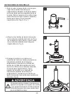
Page 28: ...espondiente a la bola para colgar del ensamble de la bola para colgar varilla C aflojando el tornillo de fijaci n de la bola hasta que sta salga libremente de la varilla Retire el pasador de la varill...

Page 29: ...y alinee la bola para colgar de manera tal que el pasador quede inserto en la ranura de la parte superior de la bola para colgar Sujete la bola para colgar firmemente al pasador Fije bien el tornillo...

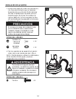
Page 30: ...ar bien asegu rada La abrazadera para colgar debe estar bien asentada contra la caja de salida Si la caja de salida est empotrada retire el panel hasta que la abrazadera haga contacto con la caja Si l...

Page 31: ...ricista certificado ya que debe tener conexi n a tierra para un funcionamiento seguro 1 Para configurar el c digo del transmisor retire la cubierta de la bater a del control remoto de mano N presionan...

Page 32: ...te conecte el conductor azul de la unidad receptora M al conductor azul de la iluminaci n del ventilador con el conector de cables 3 Deslice la unidad receptora M en el extremo abierto de la abrazader...

Page 33: ...otro Fig 5 INSTALACI N DE LA CARCASA DE LA BASE 1 Retire uno de los dos tornillos de reborde de la abrazadera para colgar Afloje el segundo tornillo de reborde sin retirarlo del todo Ensamble la base...

Page 34: ...talar el ventilador con las aspas ensambladas podr a ocasionar da os a las aspas del ventilador PRECAUCI N Aditamentos utilizados BB Tornillos con cabeza de arandela CC Arandelas de fibra x 12 x 12 NO...

Page 35: ...priete todos los tornillos Fig 1 A 3 J I 1 2 I 2 Enchufe el conector de 2 clavijas de la placa del portal mpara J al conector de 2 clavijas del ensamble del motor A Fig 2 3 Retire uno de los tres torn...

Page 36: ...ortal mparas Fig 4 4 K I 5 L J 1 ON ON ON ON ON ON ON ON INSTRUCCIONES DE FUNCIONAMIENTO DEL VENTILADOR 1 Restablezca la alimentaci n el ctrica en la caja de salida volviendo a conectar la electricida...

Page 37: ...Podr acceder a diferentes niveles de iluminaci n al presionar hacia abajo el bot n de encendido apagado de la iluminaci n Fig 3 4 Si desea que el flujo de aire corra en la direcci n opuesta apague el...

Page 38: ...e en dicha aspa H el sujetador de equilibrio del kit de equilibrio EE en el borde superior del aspa H cerca de su brazo de soporte G Fig 2 Haga funcionar el ventilador y detecte el tambaleo Detenga el...

Page 39: ...ro de plumas Evite usar agua limpiadores o pa os speros ya que pueden arruinar ela cabado Sustituci n de las bombillas Use bombillas de 40 vatios candelabro de base El ventilador emite mucho ruido 1 L...

Page 40: ...e del motor est n flojos 1 Fije bien ambos tornillos de fijaci n y sus tuercas al soporte de la varilla 2 Apriete el tornillo de fijaci n en el ensamble de la bola para colgar varilla 3 Compruebe que...

Page 41: ...n o descascaramiento Los ventiladores con acabado de lat n mantienen su belleza cuando se les protege de las cambiantes condiciones atmosf ricas La garant a no cubre los elementos de vidrio incluidos...

Page 42: ...la carcasa AP807805LAZ Ensamble de la placa del portal mpara AP807809WH Bombilla PPE12B40 Vidrio Conectores de cable Control remoto de mano Arandelas de fibra Tornillo de Tornillo con cabeza de arand...

Reviews: