background image


WARNING:

 To reduce the risk of fire, electrical shock or personal injury, wire connectors 

provided with this fan are designed to accept only one 12-gauge house wire and two lead wires 
from the fan. If your house wire is larger than 12-gauge or there is more than one house wire to 
connect to the corresponding fan lead wires, consult an electrician for the proper size wire 
connectors to use.


CAUTION:

 Be sure outlet box is properly grounded and that a ground (GREEN or BARE) 

wire is present.


WARNING:

 If house wires are different colors than referred to in the following steps, stop 

immediately. A professional electrician is recommended to determine wiring.


WARNING:

 Using a full range dimmer switch (not included) to control fan speed will cause a 

loud humming noise from fan. To reduce the risk of fire or electrical shock, do NOT use a full 
range dimmer switch to control fan speed.

WIRING

NOTE:

 This fan is remote control adaptable (remote control not included). Please refer to 

instructions provided with the remote control before proceeding with these wiring instructions.

11

Lowes.com/harborbreeze

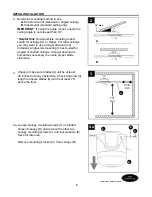
Choose wiring diagram (Fig. 1a, Fig. 1b or Fig. 1c) 
that fits your situation and make appropriate wiring 
connections as follows: [

IMPORTANT:

 Use one of the 

wire connectors (CC) provided to make each wire 
connection, making sure to screw wire connector 
(CC) on in a clockwise direction.]

1a. 

FAN AND LIGHT CONTROLLED BY PULL 

CHAINS:

 Connect BLACK and BLUE wire from fan 

to BLACK wire from ceiling. Connect WHITE wire 
from fan to WHITE wire from ceiling. Connect 
GROUND (GREEN) wires from downrod (A) and 
mounting bracket (C) to BARE/GREEN wire from 
ceiling.

 1. 

FAN AND LIGHT CONTROLLED BY TWO WALL SWITCHES

1a

FAN AND LIGHT CONTROLLED BY PULL CHAINS

120V POWER 
FROM CEILING

GREEN

WHITE

BLACK

BLUE

BLACK (POWER)

WHITE (NEUTRAL) 

GROUND/GREEN (BARE)

Summary of Contents for RLG52BNK5C3L

Page 1: ...Questions problems missing parts Before returning to your retailer call our customer service department at 1 800 643 0067 8 a m 6 p m EST Monday Thursday 8 a m 5 p m EST Friday ATTACH YOUR RECEIPT HER...

Page 2: ...ndbook if you are unfamiliar with installing electrical wiring Make sure the installation site you choose allows a minimum clearance of 7 ft from the blades to the floor and at least 30 in from the en...

Page 3: ...an electrician for the proper size wire connectors to use To reduce the risk of fire or electrical shock do not use the fan with any solid state speed control device or control fan speed with a full r...

Page 4: ...r 2 preassembled F Light Kit Fitter 1 G Blade 5 H Blade Arm 5 I Glass Shade 3 J Motor Screw 10 preassembled 1 extra DESCRIPTION PART QUANTITY PACKAGE CONTENTS 4 Lowes com harborbreeze P DESCRIPTION PA...

Page 5: ...e product Estimated Assembly Time 120 minutes Tools Required for Assembly not included Electrical Tape Phillips Screwdriver Pliers Safety Glasses Stepladder and Wire Strippers Helpful Tools not includ...

Page 6: ...ngle mount ensure the ceiling angle is not steeper than 19 Helpful Hint Downrod style mounting is best suited for ceilings 8 ft or higher For taller ceilings you may want to use a longer downrod not i...

Page 7: ...t steeper than 19 5 Remove preassembled motor screws J from underside of motor housing D If there are plastic motor blocks installed with the motor screws J discard the plastic motor blocks Note Make...

Page 8: ...nd measure 8 in of lead wire and then cut the excess wire off with wire cutters not included NOTE If you do not cut back the lead wires Steps 4 and 5 are not necessary and you may proceed to Step 6 in...

Page 9: ...one of the slots in hanging ball with tab in mounting bracket C DANGER Failure to align one of the slots in the ball with the tab may result in serious injury or death Continue to WIRING on page 11 C...

Page 10: ...he non slotted holes in the canopy B 4 3 Remove every other preassembled screw and lock washer from top of motor housing D Tab C 4 2 B Pull wires up through hole in the middle of the canopy B and atta...

Page 11: ...rical shock do NOT use a full range dimmer switch to control fan speed WIRING NOTE This fan is remote control adaptable remote control not included Please refer to instructions provided with the remot...

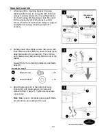
Page 12: ...opposite side of the outlet box from the BLACK and BLUE wire connections Turn spliced taped wires upward and gently push wires and wire connectors CC into outlet box 2 CC Wire Connector x 4 Hardware U...

Page 13: ...to the bottom of motor housing D with motor screws J previously removed Step 5 page 7 Tighten motor screws J securely Note Make sure to completely secure each blade arm H before proceeding to the next...

Page 14: ...lign holes in light kit fitter F with holes in switch housing Note Make sure to align notch on top edge of the light kit fitter F with the reverse switch on switch housing for the correct fit Re inser...

Page 15: ...tach pull chain extensions DD or custom pull chain extensions not included to corresponding fan and light pull chains 8 DD Pull Chain x 2 Extension Hardware Used DD OPERATING INSTRUCTIONS The fan pull...

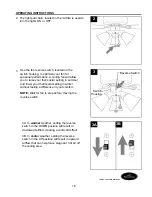
Page 16: ...t setting in summer and lower your thermostat setting in winter without feeling a difference in your comfort NOTE Wait for fan to stop before moving the reverse switch 3 3A In warmer weather setting t...

Page 17: ...enance Do not use water or a damp cloth to clean the ceiling fan Bulb Replacement Use 60 watt max candelabra base incandescent bulbs 13 watt candelabra base CFLs or 6 watt candelabra base LEDs WARNING...

Page 18: ...ation 6 Tighten yoke set screw s securely 7 Carefully loosen and lower canopy and verify that set screw on hanging ball is tightened securely TROUBLESHOOTING Fan operates but lights fail 1 Bulb s not...

Page 19: ...fective parts for the ceiling fan must be reported within the first year from the date of purchase For the balance of the warranty call our customer service department at 1 800 643 0067 for return aut...

Reviews: