8
9
ASSEMBLY INSTRUCTIONS
ASSEMBLY INSTRUCTIONS
9
8
7
Grounded/Green
Black
White
Grounded/
Green
Black
White
outlet box
black white green
white
GREEN/
GROUNDED
black
Supply circuit
receiver
Hardware Used
x4
Wire connector
AA
AA
11
CC
DD
G
F
CC
DD
Hardware Used
Decorative Screw
x
x 16
BB
Hardware Used
x 11
Blade Arm Screw
12
H
BB
FF
slot
H
10
C
Outlet box
Green/
Grounded
Receiver
Bla
ck
Bla
ck
W
hi
te
W
hi
te
G
ree
n
Screws
Wire Connector
Slot
B
A
15
Lowes.com/harborbreeze
Lowes.com/harborbreeze
Blade Screw
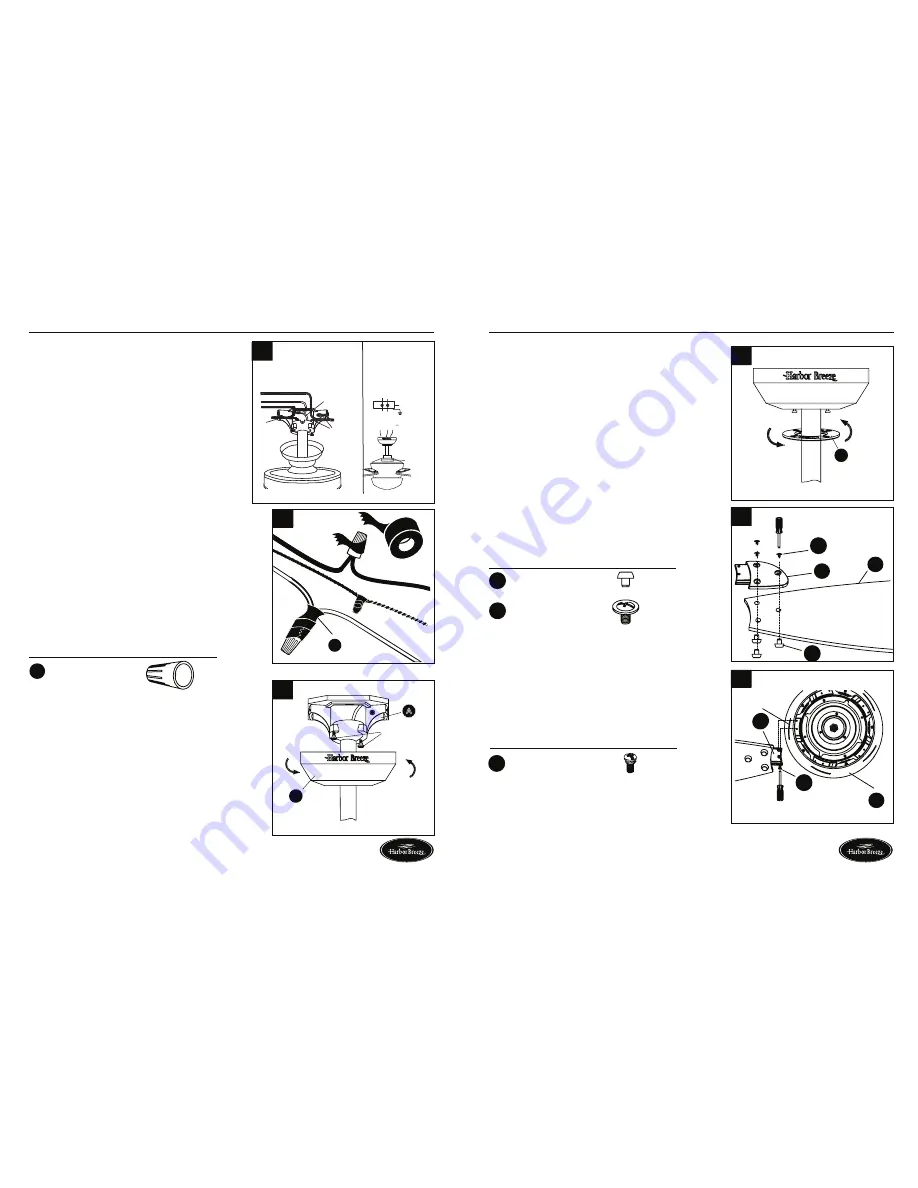
7. Connect
BLACK
wire from fan to
BLACK
wire from
ceiling. Connect
WHITE
wire from fan to
WHITE
wire from ceiling. Connect all
GROUNDED
(GREEN)
wires together from fan to
GREEN/
GROUNDED
wire from ceiling. Connecting the
GREEN/GROUNDED
wires is conducive to receive
the signal of the remote control.
Note:
BLACK
wire is hot power for fan and light kit.
WHITE
wire is common for fan and light kit.
GREEN
wire is grounded wire. lf house wires are different
colors than referred to above, stop immediately and
consult a professional electrician to determine
proper wiring.
8. Twist wire ends together and screw wire connectors (AA)
on in a clockwise direction. Tape wire connectors (AA)
and wires together with electrical tape (not included).
Note:
Wires should be spread apart with grounded
conductor and equipment-grounding conductor on one
side of outlet box and ungrounded conductor on other
side. After making connections, make sure bare wire or
wire strands are NOT visible. Place green and white
connections on opposite side of box from black and blue
connections. Splices should be turned upward and
pushed carefully up into outlet box.
9. Slide canopy (B) up against ceiling and over two screws
on mounting bracket (A). Rotate canopy (B) to lock it
into place. Tighten two screws.
10. Slide canopy cover (C) over two screws and rotate
clockwise until it locks.
Note:
Adjust screws as necessary until canopy (B) and
canopy cover (C) are snug.
11. Attach blade (G) under blade arm (F) using three
decorative screws (CC) and three blade screws (DD).
Repeat for remaining blades (G), blade arms (F),
decorative screws (CC) and blade screws (DD).
12. Insert blade assembly through slot on fan motor
assembly (H) and align two screw holes in blade
arm (F) with screw holes in fan motor assembly (H).
Secure with two blade arm screws (BB). Repeat for
remaining blade assemblies.