background image

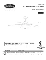
ITEM #18032

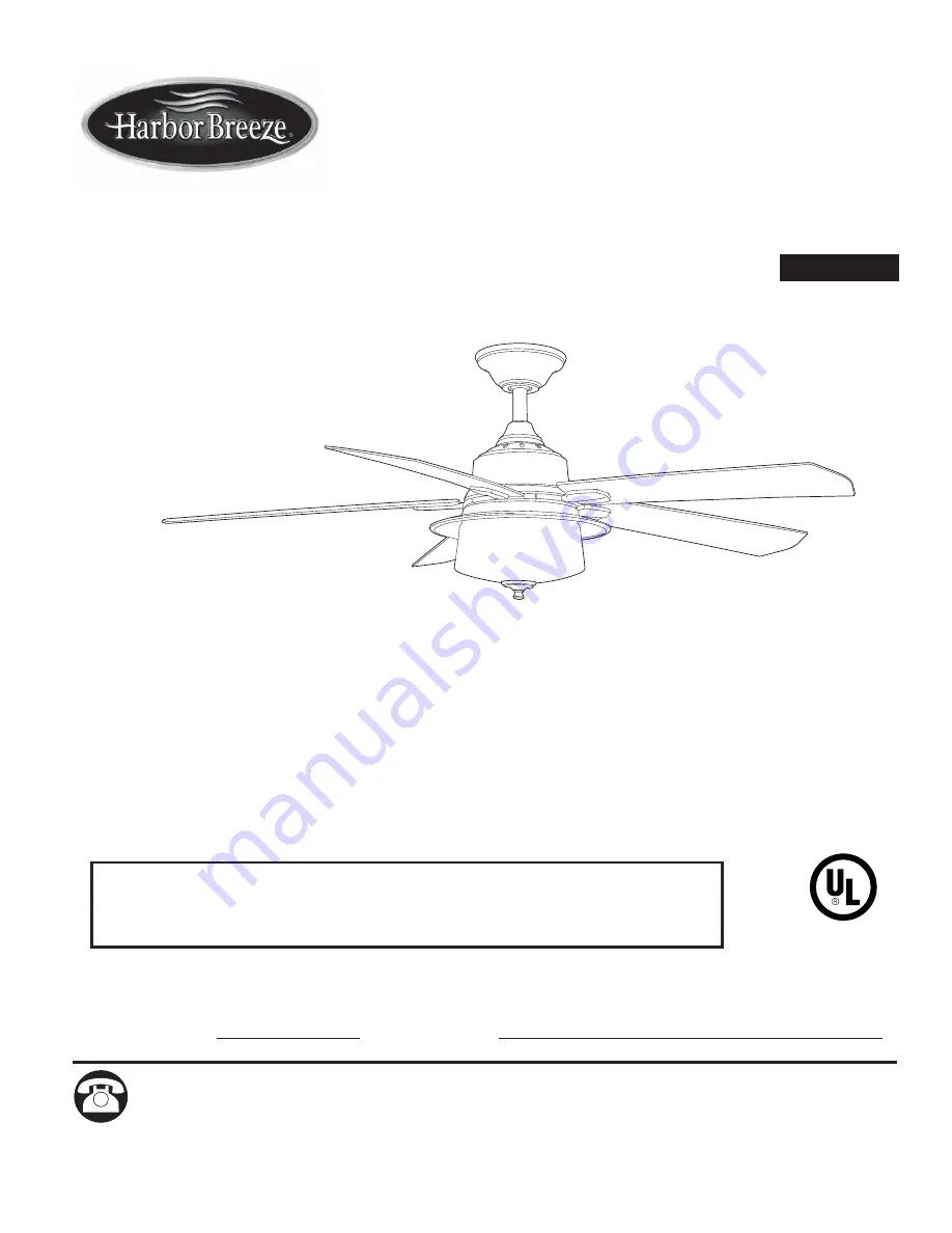
SAWGRASS CEILING FAN

MODEL #E-LUB52BNK5C1S

1

Questions, problems, missing parts?

 Before returning to your retailer, call or contact our 

customer service department at 

1-800-527-1292

, 8:30 a.m. - 5:00 p.m., CST, Monday - Friday.

ATTACH YOUR RECEIPT HERE

Serial Number

Purchase Date

español p. 20

Federal regulations require ceiling fans with light kits manufactured or imported after 
January 1, 2009, to limit total wattage consumed by the light kit to 190W.  Therefore, 
this fan is equipped with a wattage limiting device.

E192641

LISTED

For

Damp Location

Harbor Breeze® is a registered trademark 
of LF, LLC. All Rights Reserved.

Summary of Contents for SAWGRASS

Page 1: ...ST Monday Friday ATTACH YOUR RECEIPT HERE Serial Number Purchase Date espa ol p 20 Federal regulations require ceiling fans with light kits manufactured or imported after January 1 2009 to limit total...

Page 2: ...eed to be returned to the factory for repairs it must be shipped in its original packaging to ensure proper protection against damage that might exceed the initial cause for return Make sure that all...

Page 3: ...12 gauge or there is more than one house wire to connect to the two fan lead wires consult an electrician for the proper size wire connectors to use To reduce the risk of fire or electrical shock do...

Page 4: ...late Screw 3 preassembled V Pull Chain Extension 2 W Candelabra base Bulb 3 PART DESCRIPTION QUANTITY A Downrod 1 B Canopy 1 C Mounting Bracket 1 D Yoke Cover 1 E Motor Housing 1 F Blade Arm 5 G Blade...

Page 5: ...g Handbook available at Lowe s and Wire Cutters Bulbs Required included 3 candelabra base 40 watt max bulbs DANGER When using an existing outlet box make sure the outlet box is securely attached to th...

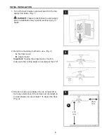
Page 6: ...s injury or death 1 Determine mounting method to use Fig 2 A Normal mount B Angle mount Important If using the angle mount check to make sure the ceiling angle is not steeper than 19 2 Check to make s...

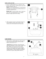
Page 7: ...lock washers K from underside of motor Fig 5 Save motor screws J and lock washers K for later use FAN MOUNTING 7 1 INITIAL INSTALLATION 4 2 Remove pin L and clip M from motor housing yoke at top of mo...

Page 8: ...excess wire off with wire cutters not included Fig 4 NOTE If you do not cut back the lead wires Steps 4 and 5 are not necessary and you may proceed to Step 6 instead 4 2 Insert downrod A through canop...

Page 9: ...NG To reduce the risk of fire electrical shock or personal injury wire connectors provided with this fan are designed to accept only one 12 gauge house wire and two lead wires from the fan If your hou...

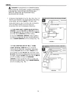
Page 10: ...L CHAINS Connect BLACK and BLUE wire from fan to BLACK wire from ceiling Connect WHITE wire from fan to WHITE wire from ceiling Connect all GROUND GREEN wires together from fan on downrod A and mounti...

Page 11: ...NOT use a full range dimmer switch to control fan speed Fig 3 3 2 3 CC CC CC CC NOTE Black wire is hot power for fan Blue wire is hot power for light kit White wire is common for fan and light kit Gr...

Page 12: ...Lift canopy B to mounting bracket C Place rounded part of slotted hole in canopy B over loosened canopy mounting screw N in mounting bracket C and push up Twist canopy B to lock Re insert canopy mount...

Page 13: ...plate P Twist fitter plate P to lock Re insert motor plate screw U that was just removed and then tighten all three motor plate screws U securely Fig 4 6 Connect large female plug from light kit fitt...

Page 14: ...g holes at the bottom of the glass shade O Align center hole in the glass shade O with threaded rod on light kit fitter H and push up gently on glass shade O until threaded rod comes through hole Alig...

Page 15: ...e attached to fan and light pull chains Fig 10 10 10 E For Light For Fan OPERATION INSTRUCTIONS The pull chain located to one side has four positions to control fan speed One pull is HIGH two is MEDIU...

Page 16: ...e moving the reverse switch 3 3 P 3A 3B 3C 3C IMPORTANT Reverse switch must be set either completely LEFT or completely RIGHT for fan to function If the reverse switch is set in the middle position Fi...

Page 17: ...use 3 Turn power off Loosen canopy B and check all connections 4 Check that the large male and female plugs in the light kit fitter H are connected properly according to instructions on page 13 Noisy...

Page 18: ...not produced by the manufacturer of this fan or affixing accessories not produced by the manufacturer of this fan are the purchaser s own responsibility Litex Industries assumes no responsibility wha...

Page 19: ...d on page 1 A D B F C G L Q H M R PART DESCRIPTION V AA U A Downrod B Canopy C Mounting Bracket D Yoke Cover F Blade Arm G Blade H Light Kit Fitter I Canopy Cover J Motor Screw K Lock Washer L Pin M C...

Page 20: ...AQU N mero de serie Fecha de compra Los reglamentos federales requieren que los ventiladores de techo con kit de iluminaci n fabricados o importados despu s del 1 de enero de 2009 tengan un l mite de...

Page 21: ...este ventilador a la f brica para realizarle reparaciones debe ser enviado en su empaque original para asegurar una protecci n adecuada contra da os que puedan aumentar la causa inicial de la devoluci...

Page 22: ...de un cable interior para conectar los dos cables conductores del ventilador preg ntele a un electricista cu l es el tama o adecuado de los conectores de cables que debe utilizar Para reducir el riesg...

Page 23: ...do V Extensi n para la cadena de tiro 2 W Bombilla de base candelabro 3 PIEZA DESCRIPCI N CANTIDAD A Varilla 1 B Base 1 C Abrazadera de montaje 1 D Cubierta de la horquilla 1 E Carcasa del motor 1 F B...

Page 24: ...en Lowe s y pinzas cortacables Bombillas requeridas se incluyen 3 bombillas de base candelabro de 40 vatios como m ximo PELIGRO Si utiliza una caja de salida existente aseg rese de que est bien sujet...

Page 25: ...e 1 Determine el m todo de instalaci n que utilizar Fig 2 A Montaje normal B Montaje en ngulo Importante Si realiza la instalaci n en ngulo verifique que el ngulo del techo no tenga una inclinaci n su...

Page 26: ...rte inferior del motor Fig 5 Guarde los tornillos del motor J y las arandelas de seguridad K para su uso posterior MONTAJE DEL VENTILADOR 26 1 INSTALACI N INICIAL 4 Retire el pasador L y el sujetador...

Page 27: ...s cables conductores los Pasos 4 y 5 no son necesarios y puede proceder con el Paso 6 en su lugar 4 2 Introduzca la varilla A a trav s de la base B la cubierta de la base I y la cubierta de la horquil...

Page 28: ...es personales los conectores de cables incluidos con este ventilador est n dise ados para soportar s lo un cable interior de calibre 12 y dos cables conductores del ventilador Si el cable interior es...

Page 29: ...ador al conductor NEGRO del techo Conecte el conductor BLANCO del ventilador al conductor BLANCO del techo Conecte todos los conductores de PUESTA A TIERRA VERDES juntos desde el ventilador en la vari...

Page 30: ...ventilador Fig 3 3 2 3 CC CC CC CC NOTA El conductor negro es el que proporciona alimentaci n al ventilador El conductor azul es el que proporciona alimentaci n al kit de iluminaci n El conductor blan...

Page 31: ...ondeada del orificio ranurado de la base B sobre el tornillo de montaje de la base N suelto en la abrazadera de montaje C y empuje hacia arriba Gire la base B para fijarla Vuelva a insertar el tornill...

Page 32: ...a bloquearla Vuelva a insertar el tornillo de la placa del motor U que acaba de retirar y luego apriete firmemente los tres tornillos de la placa del motor U Fig 4 6 Conecte el conector hembra grande...

Page 33: ...la pantalla de vidrio O Alinee el orificio central de la pantalla de vidrio O con la varilla roscada en el soporte del kit de iluminaci n H y presione la pantalla de vidrio O suavemente hacia arriba h...

Page 34: ...luz Fig 10 10 10 E para la luz V para el ventilador V INSTRUCCIONES DE FUNCIONAMIENTO La cadena de tiro ubicada a un lado tiene cuatro posiciones para controlar la velocidad del ventilador Jale una v...

Page 35: ...C IMPORTANTE El interruptor de reversa se debe configurar ya sea completamente HACIA LA IZQUIERDA o completamente HACIA LA DERECHA para que funcione el ventilador Si el interruptor de reversa se confi...

Page 36: ...base B y revise todas las conexiones 4 Verifique que los enchufes macho y hembra grandes en el soporte del kit de iluminaci n H est n bien conectados de acuerdo con las instrucciones de la p gina 32 E...

Page 37: ...ilador de techo producido por accidente uso indebido o instalaci n incorrecta o por el uso de piezas no producidas por el fabricante de este ventilador o accesorios de fijaci n que no son del fabrican...

Page 38: ...SCRIPCI N V AA U A Varilla B Base C Abrazadera de montaje D Cubierta de la horquilla F Brazo del aspa G Aspa H Soporte del kit de iluminaci n I Cubierta de la base J Tornillo del motor K Arandela de s...

Reviews: